Mitsubishi Lancer (4A9 engine). Manual - part 208
SPEAKER
CHASSIS ELECTRICAL
54A-494
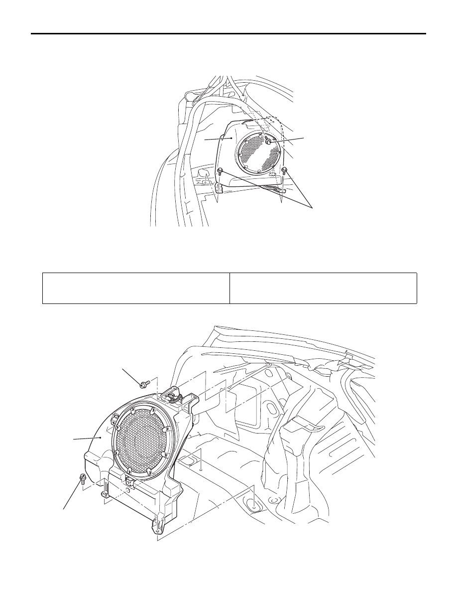
SUBWOOFER <LANCER>
SUBWOOFER <LANCER SPORTBACK>
AC608803
1
AE
5.0 ± 1.0 N·m
5.0 ± 1.0 N·m
Removal Step
1.
Rear speaker box assembly
Pre-removal operation
Removal of quarter trim (LH) (Refer to GROUP 52A
−
Quarter Trim )
Post-installation operation
Installation of quarter trim (LH) (Refer to GROUP 52A
−
Quarter Trim )
AC801904
1
AB
5.0 ± 1.0 N·m
5.0 ± 1.0 N·m