Mitsubishi Lancer (4A9 engine). Manual - part 28


  Index      Mitsubishi     Mitsubishi Lancer (4A9 engine) 12GS41 & 44S - service repair manual


Search            


Content   ..  26  27  28  29   ..


Mitsubishi Lancer (4A9 engine). Manual - part 28


CAMSHAFT

ENGINE MECHANICAL <4A9>

11A-26

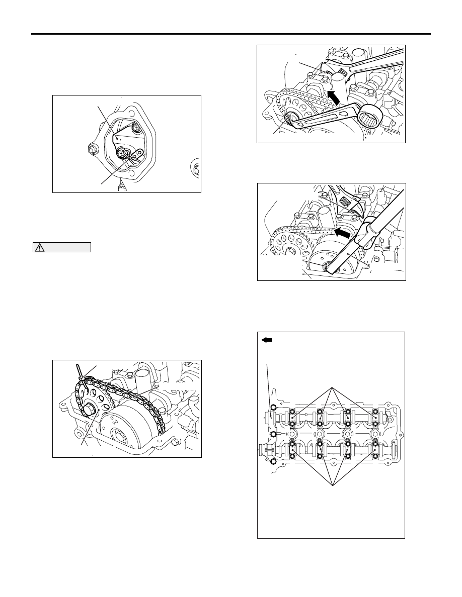
2. While holding the inlet camshaft hexagonal area 

with a wrench or a similar tool, slightly turn the 
exhaust camshaft clockwise to tighten the timing 
chain at the timing chain tensioner side and 
shorten the plunger of the timing chain tensioner.

AC311263

AB

Timing chain tensioner

Pin

3. With the plunger of the tensioner shortened, insert 

a pin or a similar tool (3 mm or less in diameter) to 
the hole shown in the illustration of the timing 
chain tensioner.

CAUTION

Do not turn the crankshaft after removing the tim-
ing chain tensioner.
4. Loosen the timing chain tensioner mounting bolts, 

and remove the timing chain tensioner from the 
timing chain case hole.

<<C>> CAMSHAFT SPROCKET/ V.V.T. 
SPROCKET ASSEMBLY/FRONT CAMSHAFT 
BEARING CAP/CAMSHAFT BEARING CAP/
CAMSHAFT REMOVAL

AC312249

AB

Timing chain

Cable band

Camshaft sprocket

1. Fix the camshaft sprocket and the timing chain 

using a cable band or a similar tool.

AC311264

AB

Hexagon part of 
the exhaust camshaft

Camshaft sprocket mounting bolt

2. While holding the exhaust camshaft hexagonal 

area with a wrench or a similar tool, loosen the 
camshaft sprocket mounting bolt.

AC311265

AC

Hexagon part of 
the inlet camshaft

V.V.T. sprocket
assembly
mounting bolt

MB991992

3. While holding the inlet camshaft hexagonal area 

using a wrench or a similar tool, use special tool 
torque wrench adapter (MB991992) to loosen the 
V.V.T. sprocket assembly mounting bolt.

AC403719

AH

1

1

2

2

1

2

3

4

3

4

3

6

5

5

6

8

7

7

8

Engine front

Front camshaft
bearing cap

Camshaft bearing cap

Camshaft bearing cap

CAMSHAFT

ENGINE MECHANICAL <4A9>

11A-27

4. Loosen the front camshaft bearing cap mounting 

bolts, and then loosen each camshaft bearing cap 
mounting bolts in the order shown. Remove the 
front camshaft bearing cap and each camshaft 
bearing cap.

CAUTION

Do not turn the crankshaft after removing the 
camshaft sprocket assembly with the timing 
chain.

AC312250

AB

Exhaust
camshaft

Camshaft sprocket
mounting bolt

Camshaft sprocket and
timing chain assembly

5. Slightly raise the exhaust camshaft with the 

camshaft sprocket and timing chain assembly 
from the cylinder head, remove the camshaft 
sprocket mounting bolt, and disconnect the 
camshaft sprocket and timing chain assembly 
from the exhaust camshaft.

6. In the same way as Step 5, disconnect the V.V.T. 

sprocket assembly and timing chain assembly 
from the inlet camshaft.

CAUTION

After disconnecting the camshaft sprocket and 
the V.V.T. sprocket assembly (with the timing 
chain for each) from the camshaft, do not dislo-
cate the camshaft sprocket, the V.V.T. sprocket 
assembly, and the timing chain.
7. After removal, place the camshaft sprocket and 

timing chain assembly, and the V.V.T. sprocket 
assembly and timing chain assembly on the 
timing chain case assembly.

<<D>> OIL FEEDER CONTROL VALVE/OIL 
FEEDER CONTROL VALVE FILTER REMOVAL

CAUTION

After removing the oil feeder control valve and 
the oil feeder control valve filter, be careful that 
no dust or other objects enter the oil passage in 
the cylinder head.

INSTALLATION SERVICE POINTS

>>A<< OIL FEEDER CONTROL VALVE FILTER 
INSTALLATION

CAUTION

When installing the oil feeder control valve filter, 
exercise special care to avoid adhesion of for-
eign objects and damage/deformation of the fil-
ter.

>>B<< O-RING/OIL FEEDER CONTROL VALVE 
INSTALLATION
1. Cover the oil groove of the oil feeder control valve 

with a cardboard.

CAUTION

When installing the O-ring to the oil feeder con-
trol valve, take care not to damage the O-ring.
2. Apply the engine oil to the O-ring and install it to 

the oil feeder control valve.

CAUTION

When installing the oil feeder control valve to the 
cylinder head, take care not to damage the O-
ring.
3. Apply the engine oil to the O-ring and install the oil 

feeder control valve to the cylinder head.

>>C<< CAMSHAFT/CAMSHAFT BEARING CAP/
FRONT CAMSHAFT BEARING CAP/ V.V.T. 
SPROCKET ASSEMBLY/CAMSHAFT SPROCKET 
INSTALLATION

AC312251

AC

V.V.T. sprocket assembly

Camshaft sprocket

Inlet camshaft

Exhaust camshaft

Dowel pin

Dowel pin

Hole

Groove

CAMSHAFT

ENGINE MECHANICAL <4A9>

11A-28

1. First, lift the V.V.T. sprocket assembly side of the 

camshaft sprocket, V.V.T. sprocket assembly and 
the timing chain assembly. Then align the dowel 
pin of the inlet camshaft with the V.V.T. sprocket 
assembly hole, and assemble the inlet camshaft 
and the V.V.T. sprocket assembly. Temporarily 
tighten the mounting bolt.

2. Next, lift the camshaft sprocket side of the 

camshaft sprocket, V.V.T. sprocket assembly and 
the timing chain assembly. Then align the dowel 
pin of the exhaust camshaft with the camshaft 
sprocket groove, and assemble the exhaust 
camshaft and the camshaft sprocket. Temporarily 
tighten the mounting bolt.

3. Place the inlet camshaft and exhaust camshaft on 

the installing location of the cylinder head.

AC205417

E 4

AB

Bearing cap No.

Identification of
inlet side and 
exhaust side

Engine front

Front mark

4. The No.2 to No.5 bearing caps are equally 

shaped for both the inlet and exhaust camshafts. 
Be sure to correctly install them by referring to the 
identification marks.

Identification mark (stamped on the front 

and No.2 to No.5 bearing caps)

I: Inlet
E: Exhaust

AC403719

AE

3

8

7

2

8

7

1

5

6

5

6

3

4

4

3

1

2

2

1

Engine front

Front camshaft
bearing cap

Camshaft bearing cap

Camshaft bearing cap

5. Tighten each camshaft bearing cap mounting 

bolts to the specified torque in the order shown, 
and then tighten the front camshaft bearing cap 
mounting bolts as well.

Tightening torque:

11 

± 1 Nm (Camshaft bearing cap mounting 

bolts)

20 

± 1 Nm (Front camshaft bearing cap mount-

ing bolts)

AC311267

AC

Hexagon part of 
the inlet camshaft

V.V.T. sprocket
assembly
mounting bolt

MB991992

6. While holding the inlet camshaft hexagonal area 

using a wrench or a similar tool, use special tool 
torque wrench adapter (MB991992) to tighten the 
V.V.T. sprocket assembly mounting bolt to the 
specified torque. Since the V.V.T. sprocket 
assembly mounting bolt is tightened by special 
tool (MB991992), calculate the tightening torque 
by the following formula.

Tightening torque: (65 

± 5) × {L ÷ (L + 150)} 

N

CAMSHAFT

ENGINE MECHANICAL <4A9>

11A-29

65 

± 5: Tightening torque of the V.V.T. sprocket 

assembly mounting bolt (unit: N

m)

L: Distance between the centre of a torque 

wrench drive and of its handle (unit: mm)

150: Length of special tool (unit: mm)

AC311268

AB

Hexagon part of 
the exhaust camshaft

Camshaft sprocket
mounting bolt

7. While holding the exhaust camshaft hexagonal 

area using a wrench or similar tool, tighten the 
camshaft sprocket mounting bolt to the specified 
torque.

Tightening torque: 92 

± 13 Nm

>>D<< TIMING CHAIN TENSIONER 
INSTALLATION

AC312123AB

Timing chain tensioner

Cam

Plunger

AC613339AB

Timing chain tensioner

Pin

Plunger

1. Install the timing chain guide, the tensioner lever 

assembly, and the timing chain tensioner.

NOTE: When the plunger of the timing chain ten-
sioner is stretched, remove the pin or the similar 
tool. While pressing the cam in the lower area of 
the timing chain tensioner, press and shorten the 
plunger to keep the status with the pin or the simi-
lar tool.

2. Tighten the timing chain tensioner mounting bolts 

to the specified torque.

Tightening torque: 9.5 

± 2.5 Nm

3. After installing the timing chain tensioner, confirm 

that the timing marks of each sprocket are aligned 
with the TDC of No.1 cylinder, and the marked link 
plate (blue-coloured area) of the timing chain is 
aligned with the specified position of each 
sprocket. Then pull out the pin or a similar tool of 
the timing chain tensioner, and apply tension to 
the timing chain.

>>E<< TIMING CHAIN TENSIONER COVER 
INSTALLATION
1. Remove the sealant from the installation face of 

the timing chain tensioner cover and the timing 
chain case assembly, and degrease the surface 
where the sealant is applied.

CAUTION

After the installation, until a sufficient period of 
time (one hour or more) elapses, do not apply the 
engine oil or water to the sealant application area 
or start the engine.

AC311269

3 mm

Timing chain case
assembly

AC


2 mm

2. Apply a bead of the specified sealant to the 

mating surface of the timing chain case assembly. 
Then, install the timing chain tensioner cover to 
the timing chain case assembly.

Specified sealant: ThreeBond 1217G or 
equivalent

NOTE: Install the timing chain tensioner cover 
immediately after the application of sealant.


Content   ..  26  27  28  29   ..