Mitsubishi Lancer (4A9 engine). Manual - part 26


  Index      Mitsubishi     Mitsubishi Lancer (4A9 engine) 12GS41 & 44S - service repair manual


Search            


Content   ..  24  25  26  27   ..


Mitsubishi Lancer (4A9 engine). Manual - part 26


AK402145

PCV valve

Plug

Vacuum gauge

AC

CRANKSHAFT PULLEY

ENGINE MECHANICAL <4A9>

11A-18

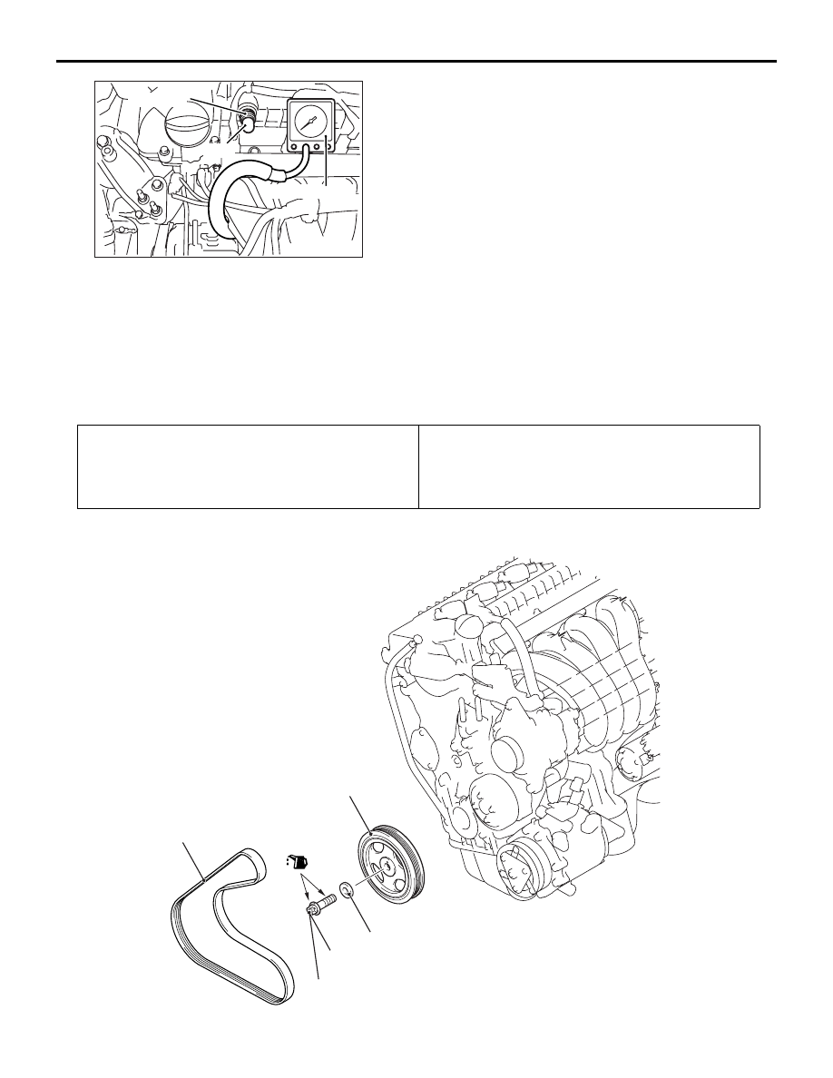
4. Disconnect the ventilation hose from the positive 

crankcase ventilation (PVC) valve, and then 
connect a vacuum gauge to the ventilation hose. 
Plug the PCV valve.

5. Start the engine and check that idle speed is 

approximately 750 r/min.

6. Check the intake manifold vacuum.

Limit: Minimum 60 kPa

7. Turn off the ignition switch.
8. Remove the vacuum gauge and then connect the 

ventilation hose to the PCV valve.

9. Remove the M.U.T.-III.

CRANKSHAFT PULLEY

REMOVAL AND INSTALLATION

M1112001604661

Pre-removal Operation
• Engine Room Under Cover Front B and Engine Room 

Side Cover (RH) Removal (Refer to GROUP 51 

− Under 

Cover ).

Post-installation Operation
• Drive belt Tension Check and Adjustment (Refer to ).
• Engine Room Under Cover Front B and Engine Room 

Side Cover (RH) Installation (Refer to GROUP 51 

− Under 

Cover ).

<Euro5>

AC613568 AD

1

3

4

2

50 N·m   +60˚   0 N·m 


50 N·m   +60˚

(Engine oil)

Removal steps 

<<

B

>>

>>

B

<<

1.

Drive belt

<<

C

>>

>>

A

<<

2.

Crankshaft pulley centre bolt

>>

A

<<

3.

Crankshaft pulley washer

>>

A

<<

4.

Crankshaft damper pulley

CRANKSHAFT PULLEY

ENGINE MECHANICAL <4A9>

11A-19

<Euro4>

ACB01385AB

2

4

5

3

50 N·m   +60˚   0 N·m 


50 N·m   +60˚

(Engine oil)

1

Removal steps 

<<

A

>>

>>

C

<<

1.

Power steering oil pump drive belt

<<

B

>>

>>

B

<<

2.

Drive belt

<<

C

>>

>>

A

<<

3.

Crankshaft pulley centre bolt

>>

A

<<

4.

Crankshaft pulley washer

>>

A

<<

5.

Crankshaft damper pulley

Removal steps (Continued)

CRANKSHAFT PULLEY

ENGINE MECHANICAL <4A9>

11A-20

REMOVAL SERVICE POINTS

<<A>> POWER STEERING OIL PUMP DRIVE 
BELT REMOVAL

CAUTION

• To reuse the drive belt, draw an arrow indicat-

ing the rotating direction on the back of the 
drive belt using chalk to install the same 
direction.

ACB01458AB

MB992276

Hang special tool drive belt remover 
(MB992276) on the vehicle components 
(including front sidemembers) using a cord 
and paper clip to prevent from falling.

1. Set the special tool in between the power steering 

oil pump pulley and the drive belt, then hold it with 
your fingers.

CAUTION

Be careful that the finger holding the special tool 
is not pinched.
2. Slightly turn the crankshaft pulley clockwise until 

the special tool is pinched and held between the 
power steering oil pump pulley and the drive belt.

3. If the special tool is held, move the finger off.

CAUTION

If the drive belt is detached, be careful that the 
special tool is also detached and fallen. 
4. Slowly turn the crankshaft pulley clockwise until 

the drive belt goes aground on the special tool 
and is detached.

5. Remove the special tool.

<<B>> DRIVE BELT REMOVAL

AC405869AB

Nut for alternator
pivot bolt

Adjusting bolt

Alternator fixing nut

1. Loosen the nut for alternator pivot bolt and 

alternator fixing nut.

CAUTION

To reuse the drive belt, draw an arrow indicating 
the rotating direction on the back of the drive belt 
using chalk to install the same direction.
2. Turn the adjusting bolt in the anti-clockwise 

direction (to the left) to remove the drive belt.

<<C>> CRANKSHAFT PULLEY CENTRE BOLT 
REMOVAL
Use the used drive belt to fix the crankshaft damper 
pulley in the following procedures, and remove the 
crankshaft pulley centre bolt.

CAUTION

• Do not use the drive belt set up on the vehi-

cles.

AC310988

ACA00760AB

Cable band

Crankshaft damper pulley

Used drive belt

Do not use a cracked or damaged drive belt.

1. Set the used drive belt as shown and hold it with a 

cable band.

CRANKSHAFT PULLEY

ENGINE MECHANICAL <4A9>

11A-21

CAUTION

Do not hang the used drive belt for the crank-
shaft rotation stopper on the water pump pulley.

AC310989

ACA00761AB

Water pump

Crankshaft damper pulley

Used drive belt

2. Turning the crankshaft damper pulley to the anti-

clockwise direction (to the left), loop the used 
drive belt around the water pump body.

3. Hold the crankshaft damper pulley and remove 

the crankshaft pulley centre bolt.

INSTALLATION SERVICE POINTS

>>A<< CRANKSHAFT DAMPER PULLEY/CRANK-
SHAFT PULLEY WASHER/CRANKSHAFT PUL-
LEY CENTRE BOLT INSTALLATION

AC608150AB

Crankshaft 
damper pulley

: Wipe clean with a rag.
: Wipe clean with a rag and degrease.
: Apply a small amount of engine oil.

Crankshaft
pulley centre bolt

Crankshaft
pulley washer

Crankshaft

Engine front

1. Wipe off the dirt on the crankshaft and the 

crankshaft damper pulley as shown in the figure 
using a rag.

2. After wiping off the dirt on the crankshaft and 

crankshaft damper pulley as shown in the figure 
using a rag, degrease the areas.

NOTE: Degrease them to prevent drop in the fric-
tion coefficient of the pressed area which is 
caused by oil adhesion.

3. Install the crankshaft damper pulley.
4. Wipe off the dirt on the crankshaft pulley washer 

and the crankshaft pulley centre bolt as shown in 
the figure using a rag.

5. Apply an adequate and minimum amount of 

engine oil to the thread of the crankshaft pulley 
centre bolt and the lower area of the flange.

CAUTION

• Do not use the drive belt set up on the vehi-

cles. 

AC310988

ACA00760AB

Cable band

Crankshaft damper pulley

Used drive belt

Do not use a cracked or damaged drive belt.

6. Set the used drive belt and hold it with a cable 

band as during removal.

CAUTION

Do not hang the used drive belt for the crank-
shaft rotation stopper on the water pump pulley.

AC310989

ACA00761AB

Water pump

Crankshaft damper pulley

Used drive belt

7. Turning the crankshaft damper pulley to the 

clockwise direction (to the right), loop the used 
drive belt around the water pump body.

8. Hold the crankshaft damper pulley and tighten the 

crankshaft pulley centre bolt to the specified 
torque.

Tightening torque: 50 N

m


Content   ..  24  25  26  27   ..