Mitsubishi Evolution X. Manual - part 967


  Index      Mitsubishi     Mitsubishi Evolution X - service repair manual 2008 year


Search            


Content   ..  965  966  967  968   ..


Mitsubishi Evolution X. Manual - part 967


FOG LIGHT

TSB Revision

CHASSIS ELECTRICAL

54A-229

.

TECHNICAL DESCRIPTION (COMMENT)

If one of the fog lights does not Illuminate, the wiring harness 
connector(s), the bulb may be defective.

.

TROUBLESHOOTING HINTS

• Burned-out fog light bulb

• Damaged harness wires and connectors

DIAGNOSIS

Required Special Tools:

• MB992006: Extra fine probe

• MB991223: Harness set

STEP 1. Check fog light (LH) connector A-43 or fog light 
(RH) A-54 for loose, corroded or damaged terminals, or 
terminals pushed back in the connector.
Q: Is fog light (LH) connector A-43 or fog light (RH) A-54 in 

good condition?
YES : 
Go to Step 2.
NO :  Repair or replace the damaged component(s). Refer 

to GROUP 00E, Harness Connector Inspection 

P.00E-2

.

STEP 2. Check the fog light bulb.
(1) Remove the fog light bulb.
(2) Verify that the fog light bulb is not damaged or burned out.
Q: Is the fog light bulb in good condition?

YES : Go to Step 3.
NO :  Replace the fog light bulb.
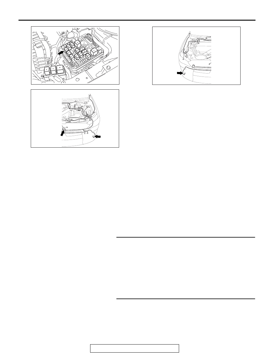
AC709111

Connector: A-15X

AH

AC708949AN

Connectors: A-43, A-50

A-43 (B)

A-50 (B)

AC708948AL

Connector: A-54

A-54 (B)

FOG LIGHT

TSB Revision

CHASSIS ELECTRICAL

54A-230

Step 3. Check the ground circuit to the fog light (LH) or fog 
light (RH). Measure the resistance at fog light (LH) 
connector A-43 or fog light (RH) connector A-54.
(1) Disconnect the connector, and measure at the wiring 

harness side.

(2) Check the resistance between the fog light connector and 

ground.

Resistance between A-43 fog light (LH) connector termi-
nal No.1 and ground

Resistance between A-54 front fog light (RH) connector 
terminal No.1 and ground

OK: The resistance should be 2 ohm or less.

Q: Is the measured resistance 2 ohms or less?

YES : Go to Step 5.
NO :  Go to Step 4.

Step 4. Check the wiring harness between fog light (LH) 
connector A-43 (terminal 1) or fog light (RH) connector 
A-54 (terminal 1) and ground.
NOTE: Also check intermediate connector A-50 for loose, cor-
roded, or damaged terminals, or terminals pushed back in the 
connector. If intermediate connector A-50 is damaged, repair or 
replace the connector as described in GROUP 00E, Harness 
Connector Inspection 

P.00E-2

.

• Check the ground wires for open circuit.

Q: Is the wiring harness between fog light (LH) connector 

A-43 (terminal 1) or fog light (RH) connector A-54 
(terminal 1) and ground in good condition?
YES : 
The trouble can be an intermittent malfunction (Refer 

to GROUP 00, How to use 
Troubleshooting/inspection Service Points, How to 
Cope with Intermittent Malfunction 

P.00-15

).

NO :  The wiring harness may be damaged or the 

connector(s) may have loose, corroded or damaged 
terminals, or terminals pushed back in the connector. 
Repair the wiring harness as necessary.

AC608255 AX

Harness side: A-34

AC608255 AY

Harness side: A-44

FOG LIGHT

TSB Revision

CHASSIS ELECTRICAL

54A-231

STEP 5. Check fog light relay connector A-15X for loose, 
corroded or damaged terminals, or terminals pushed back 
in the connector.
Q: Is fog light relay connector A-15X in good condition?

YES : Go to Step 6.
NO :  Repair or replace the damaged component(s). Refer 

to GROUP 00E, Harness Connector Inspection 

P.00E-2

.

STEP 6. Check the wiring harness between fog light (LH) 
connector A-43 (terminal 2) or fog light (RH) connector 
A-54 (terminal 2) and fog light relay connector A-15X 
(terminal 3).
NOTE: Also check intermediate connector A-50 for loose, cor-
roded, or damaged terminals, or terminals pushed back in the 
connector. If intermediate connector A-50 is damaged, repair or 
replace the connector as described in GROUP 00E, Harness 
Connector Inspection 

P.00E-2

.

• Check the power supply line for open circuit.

Q: Is the wiring harness between fog light (LH) connector 

A-43 (terminal 2) or fog light (RH) connector A-54 
(terminal 2) and fog light relay connector A-15X 
(terminal 3) in good condition?
YES : 
Go to Step 7.
NO :  The wiring harness may be damaged or the 

connector(s) may have loose, corroded or damaged 
terminals, or terminals pushed back in the connector. 
Repair the wiring harness as necessary.

STEP 7. Retest the system.
Q: Does the right or left fog light does not illuminate in 

good condition?
YES : 
The trouble can be an intermittent malfunction (Refer 

to GROUP 00, How to use 
Troubleshooting/inspection Service Points, How to 
Cope with Intermittent Malfunction 

P.00-15

).

NO :  Replace the fog light(s).

FOG LIGHT

TSB Revision

CHASSIS ELECTRICAL

54A-232

Inspection Procedure 3: The front fog light indicator does not illuminate normally.

CAUTION

Whenever the ECU is replaced, ensure that the power supply circuit, the ground circuit and the com-
munication circuit are normal.

.

TECHNICAL DESCRIPTION (COMMENT)

If the fog light indicator does not illuminate normally, 
connector(s), wiring harness in the CAN bus lines, 
the ETACS-ECU or the combination meter may be 
defective.

.

TROUBLESHOOTING HINTS

• The ETACS-ECU may be defective

• The combination meter may be defective

• Damaged harness wires and connectors

DIAGNOSIS

Required Special Tools:

• MB991223: Harness Set

• MB991958: Scan Tool (M.U.T.-III Sub Assembly)

• MB991824: V.C.I.

• MB991827: M.U.T.-III USB Cable

• MB991910: M.U.T.-III Main Harness A

STEP 1. Check the fog lights.
When the fog light switch is operated, check that the fog lights 
illuminate and go off normally.
Q: Is the fog lights normal?

YES : Go to Step 2.
NO :  First, repair the front fog lights. Refer to Inspection 

Procedure 2 "The right or left fog light does not 
illuminate 

P.54A-228

."

INPUT SIGNAL

ETACS-ECU

COMBINATION
METER

CAN COMMUNICATION LINE
(CAN_L LINE)

CAN COMMUNICATION LINE
(CAN_H LINE)

Front Fog Light Indicator Light Circuit

FRONT FOG LIGHT
SWITCH


Content   ..  965  966  967  968   ..