Mitsubishi Evolution X. Manual - part 966


  Index      Mitsubishi     Mitsubishi Evolution X - service repair manual 2008 year


Search            


Content   ..  964  965  966  967   ..


Mitsubishi Evolution X. Manual - part 966


FOG LIGHT

TSB Revision

CHASSIS ELECTRICAL

54A-225

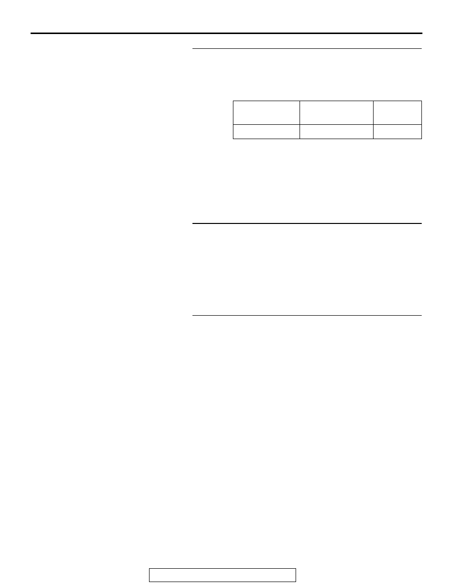
STEP 4. Using scan tool MB991958, check data list.
Use the ETACS-ECU data list to check the signals related to 
the fog light function.

• Turn the ignition switch to the "ACC" position.

• Turn the fog light switch to ON.

Q: Does scan tool MB991958 display the items "Front fog 

light" as normal condition?
YES : 
Go to Step 5.
NO :  Troubleshoot the ETACS-ECU. Refer to ETACS, 

Diagnosis - Inspection Procedure 12 "ETACS-ECU 
does not receive any signal from the column switch 
signal." 

P.54A-639

.

STEP 5. Check fog light relay connector A-15X for loose, 
corroded or damaged terminals, or terminals pushed back 
in the connector.
Q: Is fog light relay connector A-15X in good condition?

YES : Go to Step 6.
NO :  Repair or replace the damaged component(s). Refer 

to GROUP 00E, Harness Connector Inspection 

P.00E-2

.

STEP 6. Check the fog light relay.
Refer to 

P.54A-237

.

Q: Is the fog light relay in good condition?

YES : Go to Step 7.
NO :  Replace the fog light relay.

Item No.

Item name

Normal 
condition

Item 212

Front fog light

ON

FOG LIGHT

TSB Revision

CHASSIS ELECTRICAL

54A-226

STEP 7. Check the battery power supply circuit to the fog 
light relay. Measure the voltage at fog light relay connector 
A-15X.

CAUTION

The top and bottom of the fog light relay are difficult to 
identify. Prior to inspection, confirm the triangle mark on 
the relay box.
(1) Disconnect fog light relay connector A-15X and measure 

the voltage available at the relay box side of the connector.

(2) Measure the voltage between terminal 2 and ground, and 

between terminal 4 and ground.

• The voltage should measure approximately 12 volts 

(battery positive voltage).

Q: Is the measured voltage approximately 12 volts (battery 

positive voltage)?
YES : 
Go to Step 9.
NO :  Go to Step 8.

STEP 8. Check the wiring harness between fog light relay 
connector A-15X (terminal 2 and 4) and fusible link (36).

• Check the power supply line for open circuit.

Q: Is the wiring harness between fog light relay connector 

A-15X (terminal 2 and 4) and fusible link (36) in good 
condition?
YES : 
Go to Step 13.
NO :  The wiring harness may be damaged or the 

connector(s) may have loose, corroded or damaged 
terminals, or terminals pushed back in the connector. 
Repair the wiring harness as necessary.

STEP 9. Check ETACS-ECU connector C-312 for loose, 
corroded or damaged terminals, or terminals pushed back 
in the connector.
Q: Is ETACS-ECU connector C-312 in good condition?

YES : Go to Step 10.
NO :  Repair or replace the damaged component(s). Refer 

to GROUP 00E, Harness Connector Inspection 

P.00E-2

.

AC608254 BA

Relay box side: A-11X

FOG LIGHT

TSB Revision

CHASSIS ELECTRICAL

54A-227

STEP 10. Check the wiring harness between fog light relay 
connector A-15X (terminal 1) and ETACS-ECU connector 
C-312 (terminal 4).
Q: Is the wiring harness between fog light relay connector 

A-15X (terminal 1) and ETACS-ECU connector C-312 
(terminal 4) in good condition?
YES : 
Go to Step 11.
NO :  The wiring harness may be damaged or the 

connector(s) may have loose, corroded or damaged 
terminals, or terminals pushed back in the connector. 
Repair the wiring harness as necessary.

STEP 11. Check the wiring harness between fog light relay 
connector A-15X (terminal 3) and fog light (LH) connector 
A-43 (terminal 2) or fog light (RH) connector A-54 (terminal 
2).
NOTE: Also check intermediate connector A-50 for loose, cor-
roded, or damaged terminals, or terminals pushed back in the 
connector. If intermediate connector A-50 is damaged, repair or 
replace the connector as described in GROUP 00E, Harness 
Connector Inspection 

P.00E-2

.

• Check the power supply line for open circuit.

Q: Is the wiring harness between fog light relay connector 

A-15X (terminal 3) and fog light (LH) connector A-43 
(terminal 2) or fog light (RH) connector A-54 (terminal 2) 
in good condition?
YES : 
Go to Step 12.
NO :  The wiring harness may be damaged or the 

connector(s) may have loose, corroded or damaged 
terminals, or terminals pushed back in the connector. 
Repair the wiring harness as necessary.

STEP 12. Check the wiring harness between fog light (LH) 
connector A-43 (terminal 1) or fog light (RH) connector 
A-54 (terminal 1) and ground.
NOTE: Also check intermediate connector A-50 for loose, cor-
roded, or damaged terminals, or terminals pushed back in the 
connector. If intermediate connector A-50 is damaged, repair or 
replace the connector as described in GROUP 00E, Harness 
Connector Inspection 

P.00E-2

.

• Check the ground wires for open circuit.

Q: Is the wiring harness between fog light (LH) connector 

A-43 (terminal 1) or fog light (RH) connector A-54 
(terminal 1) and ground in good condition?
YES : 
Go to Step 13.
NO :  The wiring harness may be damaged or the 

connector(s) may have loose, corroded or damaged 
terminals, or terminals pushed back in the connector. 
Repair the wiring harness as necessary.

FOG LIGHT

TSB Revision

CHASSIS ELECTRICAL

54A-228

STEP 13. Retest the system.
Q: Does the fog lights illuminate in good condition?

YES : The trouble can be an intermittent malfunction (Refer 

to GROUP 00, How to use 
Troubleshooting/inspection Service Points, How to 
Cope with Intermittent Malfunction 

P.00-15

).

NO :  Replace the ETACS-ECU.

Inspection Procedure 2: One of the fog lights does not illuminate.

Fog Light Circuit

FOG LIGHT
RELAY

RELAY BOX

ENGINE 
COMPARTMENT

FOG LIGHT
(LH)              (RH)


Content   ..  964  965  966  967   ..