Mitsubishi Evolution X. Manual - part 964


  Index      Mitsubishi     Mitsubishi Evolution X - service repair manual 2008 year


Search            


Content   ..  962  963  964  965   ..


Mitsubishi Evolution X. Manual - part 964


FOG LIGHT

TSB Revision

CHASSIS ELECTRICAL

54A-217

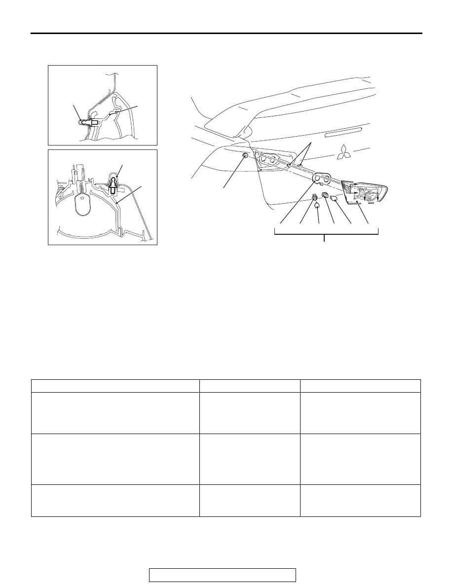
TAILLIGHT REMOVAL AND INSTALLATION

M1541402600107

FOG LIGHT

SERVICE SPECIFICATIONS

M1540400900091

AC706935AC

4.5 ± 1.5 N·m 
40 ± 13 in-lb

Grommet

Section A - A

Grommet

Section B - B

2

2

2

4

5

6

7

3

1

A

A

8

B

B

Removal Steps 

Trunk lid trim (Refer to GROUP 52A 
− Trims 

P.52A-11

).

1.

Taillight assembly

2.

Taillight unit

3.

Back-up light bulb

4.

Socket

5.

Taillight bulb

6.

Socket

7.

Gasket

8.

Grommet

Removal Steps (Continued)

Item

Standard value

Limit

Fog light aiming (cutoff line direction) [at 7.62 
m (25.0 ft)]

The horizontal line 153.0 
mm (6.02 inches) (1.15 
degrees angle) below the 
horizontal line (H)

Fog light aiming (vertical direction) [at 7.62 m 
(25.0 ft)]

Area from 53.2 mm (2.09 
inches) (0.4 degrees angle) 
above the cutoff line to 99.8 mm 
(3.93 inches) (0.75 degrees 
angle) below the cutoff line

Fog light aiming (horizontal direction) [at 7.62 
m (25.0 ft)]

Vertical line (V) 

± 599.7 mm  

(

± 23.6 inches) (± 4.5 degrees 

angle).

FOG LIGHT

TSB Revision

CHASSIS ELECTRICAL

54A-218

SPECIAL TOOLS

M1540401800075

Tool

Tool number and 
name

Supersession

Application

MB990784
Ornament remover

General service 
tool

Removal of front fog light bezel

MB991958

a. MB991824
b. MB991827
c. MB991910
d. MB991911
e. MB991914
f. MB991825
g. MB991826

M.U.T.-III 
sub-assembly

a. Vehicle 

communication 
interface (V.C.I.)

b. M.U.T.-III USB 

cable

c. M.U.T.-III main 

harness A 
(Vehicles with 
CAN 
communication 
system)

d. M.U.T.-III main 

harness B 
(Vehicles without 
CAN 
communication 
system)

e. M.U.T.-III main 

harness C (for 
Daimler Chrysler 
models only)

f. M.U.T.-III 

measurement 
adapter

g. M.U.T.-III trigger 

harness

MB991824-KIT
NOTE: G: 
MB991826 
M.U.T.-III Trigger 
Harness is not 
necessary when 
pushing V.C.I. 
ENTER key.

CAUTION

M.U.T.-III main harness A 
(MB991910) should be used. 
M.U.T.-III main harness B and C 
should not be used for this 
vehicle.
DTC, data list and actuator test 
check.

MB990784

MB991910

MB991826

MB991958

MB991911

MB991914

MB991824

MB991827

MB991825

DO NOT USE

a

b

c

d

e

f

g

DO NOT USE

FOG LIGHT

TSB Revision

CHASSIS ELECTRICAL

54A-219

DIAGNOSIS

STANDARD FLOW OF DIAGNOSTIC 
TROUBLESHOOTING

M1540401700012

Refer to GROUP 00,  How to use Troubleshooting/inspection 
Service Points, Troubleshooting Content

P.00-7

.

DIAGNOSTIC FUNCTION

M1540403000020

HOW TO CONNECT THE SCAN TOOL (M.U.T.-III)

.

REQUIRED SPECIAL TOOLS:

MB991958: Scan Tool (M.U.T.-III Sub Assembly)

• MB991824: Vehicle Communication Interface (V.C.I.)

• MB991827: M.U.T.-III USB Cable

• MB991910: M.U.T.-III Main Harness A (Vehicles with CAN 

communication system)

.

MB991223

a. MB991219
b. MB991220
c. MB991221
d. MB991222

Harness set

a. Check harness
b. LED harness
c. LED harness 

adapter

d. Probe

General service 
tool (jumper)

Continuity check and voltage 
measurement at harness wire or 
connector

a. For checking connector pin 

contact pressure

b. For checking power supply circuit
c. For checking power supply circuit
d. For connecting a locally sourced 

tester

MB992006
Extra fine probe

Continuity check and voltage 
measurement at harness wire or 
connector

Tool

Tool number and 
name

Supersession

Application

MB991223

a

d

c

b

DO NOT USE

BA

MB992006

FOG LIGHT

TSB Revision

CHASSIS ELECTRICAL

54A-220

CAUTION

To prevent damage to scan tool MB991958, always turn the 
ignition switch to the "LOCK" (OFF) position before con-
necting or disconnecting scan tool MB991958.
1. Ensure that the ignition switch is at the "LOCK" (OFF) 

position.

2. Start up the personal computer.
3. Connect special tool MB991827 to special tool MB991824 

and the personal computer.

4. Connect special tool MB991910 to special tool MB991824.
5. Connect special tool MB991910 to the data link connector.
6. Turn the power switch of special tool MB991824 to the "ON" 

position.
NOTE: When special tool MB991824 is energized, special 
tool MB991824 indicator light will be illuminated in a green 
color.

7. Start the scan tool system on the personal computer.
NOTE: Disconnecting scan tool MB991958 is the reverse of the 
connecting sequence, making sure that the ignition switch is at 
the "LOCK" (OFF) position.

HOW TO READ AND ERASE DIAGNOSTIC 
TROUBLE CODES

.

REQUIRED SPECIAL TOOLS:

MB991958: Scan Tool (M.U.T.-III Sub Assembly)

• MB991824: Vehicle Communication Interface (V.C.I.)

• MB991827: M.U.T.-III USB Cable

• MB991910: M.U.T.-III Main Harness A (Vehicles with CAN 

communication system)

.

CAUTION

To prevent damage to scan tool MB991958, always turn the 
ignition switch to the "LOCK" (OFF) position before con-
necting or disconnecting scan tool MB991958.
NOTE: If the battery voltage is low, diagnostic trouble codes will 
not be set. Check the battery if scan tool MB991958 does not 
display.
1. Connect scan tool MB991958 to the data link connector.
2. Turn the ignition switch to the "ON" position.
3. Select "System select" from the start-up screen.
4. Select "From 2006 MY" of "Model Year." When the "Vehicle 

Information" is displayed, check the contents.

5. Select "ETACS" from "System List", and press the "OK" 

button.
NOTE: When the "Loading Option Setup" list is displayed, 
check the applicable item.

6. Select "Diagnostic Trouble Code."
7. If a DTC is set, it is shown.
8. Choose "Erase DTCs" to erase the DTC.

AC608435

Data link connector

MB991827

MB991824

MB991910

AB


Content   ..  962  963  964  965   ..