Mitsubishi Evolution X. Manual - part 932


  Index      Mitsubishi     Mitsubishi Evolution X - service repair manual 2008 year


Search            


Content   ..  930  931  932  933   ..


Mitsubishi Evolution X. Manual - part 932


COMBINATION METER

TSB Revision

CHASSIS ELECTRICAL

54A-89

ON-VEHICLE SERVICE

SPEEDOMETER CHECK

M1540201400374

1. Adjust the pressure of tires to the specified level (Refer to 

GROUP 31, On-vehicle Service 

P.31-8

).

2. Where applicable, ensure that the TPMS warning light is not 

illuminating or flashing.

CAUTION

Do not accelerate or decelerate suddenly during servicing 
work.
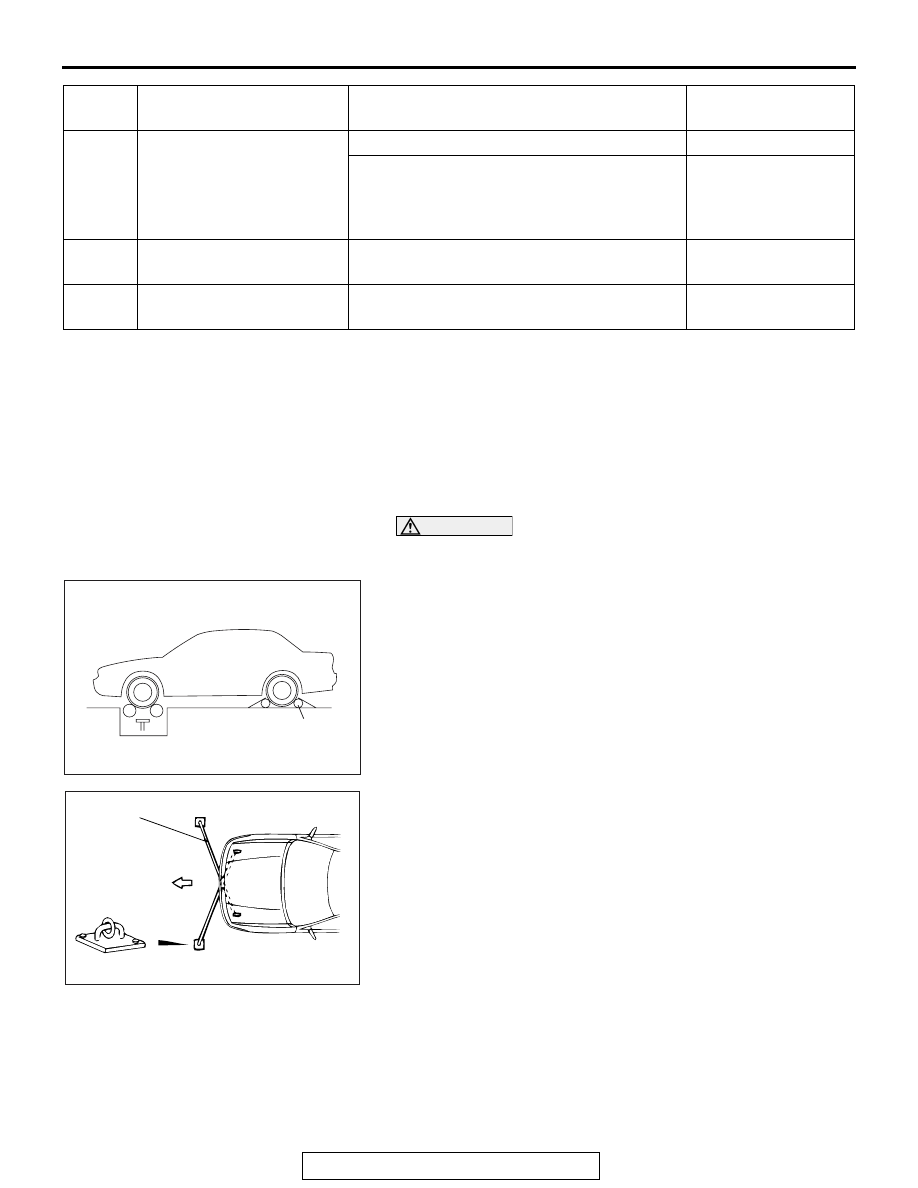
3. Set the vehicle onto a speedometer tester and place the rear 

wheels on a free roller.

4. To prevent the wheel from moving from side to side, attach 

tension bars to the tie-down hook, and secure both ends to 
anchor plates.

5. To prevent the vehicle from moving, attach a chain or wire to 

the rear retraction hook, and make sure the end of the chain 
or wire is secured.

6. Check if the speedometer indicator range is within the 

standard values.

22

Illumination (

−) output

With daytime lighting control

0 V

With nighttime lighting control

In accordance with 
the rheostat switch 
operation, a pulse is 
generated.

23

Illumination (+) output

With lighting control

Battery positive 
voltage

24

Illumination (power supply) Always

Battery positive 
voltage

Termina
l No.

Check item

Check condition

Normal condition

AC705417

Free roller

AD

AC001288

Front

AC

Tension bar

Anchor plate

COMBINATION METER

TSB Revision

CHASSIS ELECTRICAL

54A-90

Standard value <Except vehicles for CANADA>:

Standard value <Vehicles for CANADA>:

7. If not within the standard value, check the tire size. If an 

incorrect size of tire is used, replace it and check again. If 
the tire size is correct, a defect may be present in 
components and circuit between the ASC and the 
combination meter. Check the following items.

• ASC (refer to GROUP 35C, Diagnosis 

P.35C-20

).

• Combination meter (refer to 

P.54A-28

).

Standard indication {mph 
(km/h)}

Allowance range {mph 
(km/h)}

10 (16)

8.5 

− 11.5 (13.6 − 18.4)

25 (40)

23.5 

− 26.5 (37.6 − 42.4)

50 (80)

48.5 

− 51.5 (77.6 − 82.4)

75 (120)

73.5 

− 76.5 (117.6 − 122.4)

100 (161)

98.5 

− 102.5 (158.6 − 165.0)

125 (201)

123.5 

− 127.5 (198.6 − 205.0)

150 (241)

148.5 

− 153.5 (239.0 − 247.0)

175 (282)

173.5 

− 179.0 (279.2 − 288.0)

standard indication {km/h 
(mph)}

Allowance range {km/h 
(mph)}

20 (12.4)

19 

− 24 (11.8 − 14.9)

40 (24.8)

40 

− 44 (24.8 − 27.3)

80 (49.7)

80 

− 85 (49.7 − 52.8)

120 (74.6)

120.5 

− 125.5 (74.9 − 78.0)

160 (99.4)

160.5 

− 165.5 (99.7 − 102.8)

200 (124.3)

200.5 

− 207.0 (124.6 − 128.6)

240 (149.1)

240.5 

− 247.0 (149.4 − 153.5)

280 (174.0)

280.5 

− 289.0 (174.3 − 179.6)

COMBINATION METER

TSB Revision

CHASSIS ELECTRICAL

54A-91

TACHOMETER CHECK

M1540201500177

When the actuator tests (item No.2) are performed using scan 
tool MB991958, check that the tachometer indication error is 
within the standard value.
NOTE: Values in ( ) indicates the reference value.

Standard value:

FUEL LEVEL SENSOR CHECK

M1540201600356

.

1. Remove the rear seat (Refer to GROUP 52A 

− Rear Seat 

Assembly 

P.52A-25

).

2. Remove the floor inspection lid, and then remove the fuel 

pump module (Refer to GROUP 13B 

− Fuel Tank 

P.13B-10

).

.

NOMINAL RESISTANCE OF THE FUEL LEVEL 
SENSOR

When float of the fuel level sensor is in stopper positions F and 
E, ensure that resistance between the fuel level sensor terminal 
and ground terminal is within the standard value.

Standard value: 

When the float is moved slowly between stopper positions "F" 
and "E", ensure that the resistance is smoothly changing.

.

Engine speed (r/min) Tachometer indicating 

error (r/min)

600

550 

− 650

(2,000)

(1,950 

− 2,050)

3,000

2,950 

− 3,050

(4,000)

(3,950 

− 4,050)

5,000

4,950 

− 5,050

6,000

5,950 

− 6,050

(7,000)

(6,950 

− 7,050)

(8,000)

(7,950 

− 8,050)

Float position

Gauge resistance value 
(ohms)

Main

Sub

Stopper position "F"

6.5 

± 1.0

6.5 

± 1.0

Stopper position "E"

41.9 

± 1.0

78.1 

± 1.0

AC705651

<Main>

<Sub>

AD

F stopper position

E stopper position

COMBINATION METER

TSB Revision

CHASSIS ELECTRICAL

54A-92

FUEL LEVEL SENSOR FLOAT HEIGHT

When float is moved to contact the float arm on the stopper, 
ensure that stopper positions "F" (height A) and "E" (height B) 
are within the standard value.

Standard value:

MULTI INFORMATION METER SWITCH CHECK

M1540202000164

Float position

Float height [mm (in)]

Main

Sub

Stopper position "F" 
(height A)

140.9 (5.5)

14.2 

± 3.0  

(0.5 

± 0.1)

Stopper position "E" 
(height B)

39.1 (1.5)

179.3 

± 3.0 (7.0 

± 0.1)

AC705598AD

B

A

<Main>

<Sub>

A

B

E stopper point

E stopper point

F stopper point

F stopper point

Switch position

Tester connection Specified condition

Pressed

1-4

Continuity exists 


(2 ohms or less)

Released

1-4

Open circuit

AC505421AD


Content   ..  930  931  932  933   ..