Mitsubishi Evolution X. Manual - part 623


  Index      Mitsubishi     Mitsubishi Evolution X - service repair manual 2008 year


Search            


Content   ..  621  622  623  624   ..


Mitsubishi Evolution X. Manual - part 623


DIAGNOSIS

TSB Revision

WIRELESS CONTROL MODULE (WCM)

42C-109

STEP 5. Check the trunk lid latch assembly.
Remove the trunk lid latch assembly. Refer to GROUP 42A, 
Trunk lid removal and installation 

P.42A-147

.

Q: Is the trunk lid latch normal?

YES : Go to Step 6.
NO :  Replace the trunk lid latch assembly.

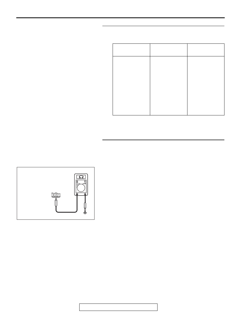
STEP 6. Check the ground circuit to the trunk lid latch. 
Measure the resistance at trunk lid latch connector F-19.
(1) Disconnect trunk lid latch connector F-19 and measure the 

resistance available at the wiring harness side of the 
connector.

(2) Measure the resistance value between terminal 2 and 

ground.

• The resistance should be 2 ohms or less.

Q: Is the measured resistance 2 ohms or less?

YES : Go to Step 9.
NO :  Go to Step 7.

Lever position

Battery 
connection

Lever operation

At the "LOCK" 
position

• Connect 

terminal No.2 
and the 
negative 
battery 
terminal.

• Connect 

terminal No.3 
and the 
positive battery 
terminal.

The lever moves 
from the "LOCK" 
position to the 
"UNLOCK" 
position.

AC209731

Connector F-19
(harness side)

AC208731CD

DIAGNOSIS

TSB Revision

WIRELESS CONTROL MODULE (WCM)

42C-110

STEP 7. Check the wiring harness between the trunk lid 
latch connector F-19 (terminal No. 2) and the ground for 
open circuit.
(1) Disconnect trunk lid latch connector F-19 and ground, and 

check the wiring harness.

(2) Check the wiring harness between trunk lid latch connector 

F-19 (terminal No. 2) and ground.

OK: Continuity exists (2 

 or less)

Q: Is the wiring harness between trunk lid latch connector 

F-19 (terminal No. 2) and ground in good condition?
YES  : 
Go to Step 8.
NO (trunk lid latch connector F-19 terminal No. 2 


ground.) : Repair the wiring harness between trunk lid latch 

connector F-19 (terminal No. 2) and ground.

STEP 8. Check the wiring harness between the trunk lid 
latch connector F-19 (terminal No. 2) and the ground for 
open circuit.
(1) Disconnect trunk lid latch connector F-19 and ground, and 

check the wiring harness.

(2) Check the wiring harness between trunk lid latch connector 

F-19 (terminal No. 2) and ground.

OK: Continuity exists (2 

 or less)

Q: Is the wiring harness between trunk lid latch connector 

F-19 (terminal No. 2) and ground in good condition?
YES  : 
Go to Step 11.
NO (trunk lid latch connector F-19 terminal No. 2 


ground.) : Repair the wiring harness between trunk lid latch 

connector F-19 (terminal No. 2) and ground.

STEP 9. Check the wiring harness between the trunk lid 
latch connector F-19 (terminal No. 3) and the ETACS-ECU 
connector C-311 (terminal No. 1) for open circuit.
(1) Disconnect trunk lid latch connector F-19 and ETACS-ECU 

connector C-311, and check the wiring harness.

(2) Check the wiring harness between trunk lid latch connector 

F-19 (terminal No. 3) and ETACS-ECU connector C-311 
(terminal No. 1).

OK: Continuity exists (2 

 or less)

Q: Is the wiring harness between trunk lid latch connector 

F-19 (terminal No. 3) and ETACS-ECU connector C-311 
(terminal No. 1) in good condition?
YES  : 
Go to Step 10.
NO (trunk lid latch connector F-19 terminal No. 3 


ETACS-ECU connector C-311 terminal No. 1.) : Repair 

the wiring harness between trunk lid latch connector 
F-19 (terminal No. 3) and ETACS-ECU connector 
C-311 (terminal No. 1).

AC209731

Connector F-19
(harness side)

AC208731CD

AC209731

Connector F-19
(harness side)

AC208731CD

AC709707HP

Harness side: F-19

Harness side: C-311

DIAGNOSIS

TSB Revision

WIRELESS CONTROL MODULE (WCM)

42C-111

STEP 10. Check the wiring harness between the trunk lid 
latch connector F-19 (terminal No. 3) and the ground for 
short circuit.
(1) Disconnect  trunk lid latch connector F-19, and check the 

wiring harness.

(2) Check the wiring harness between trunk lid latch connector 

F-19 (terminal No. 3) and ground

OK: No continuity

Q: Is the wiring harness between trunk lid latch connector 

F-19 (terminal No. 3) and the ground in good condition?
YES  : 
Go to Step 11.
NO (trunk lid latch connector F-19 terminal No. 3 


ground.) : Repair the wiring harness between trunk lid latch 

connector F-19 (terminal No. 3) and ground.

STEP 11. Check of the troubles
Operate the transmitter and check that the trunk lid can be 
opened.
Q: Is the check result normal?

YES : The diagnosis is complete.
NO :  Replace the ETACS-ECU. When the ETACS-ECU is 

replaced, register the keyless ID. Refer to 

P.42C-114

The trunk lid can be opened by means of the 
transmitter.

INPUT SIGNAL REFERENCE TABLE

M1427504700021

INPUT SIGNAL PROCEDURES

Signals from transmitter switches are not received.

CAUTION

Before replacing the ECU, ensure that the power 
supply circuit, the ground circuit and the com-
munication circuit are normal.

.

TECHNICAL DESCRIPTION (COMMENT)

Input signal from the keyless entry transmitter is 
used to operate the keyless entry system. If the sig-
nal is abnormal, the keyless entry system will not 
work normally.

.

TROUBLESHOOTING HINTS

• Battery discharged in the transmitter

• Malfunction of the transmitter

• Malfunction of WCM

AC209731

Connector F-19
(harness side)

AC208731CK

Trouble symptom

Reference page

Signals from transmitter switches are not received.

P.42C-111

DIAGNOSIS

TSB Revision

WIRELESS CONTROL MODULE (WCM)

42C-112

DIAGNOSIS

Required Special Tools:

• MB992006: Extra fine probe

• MB991223: Harness set

• MB991958: Scan Tool (M.U.T.-III Sub Assembly)

• MB991824: Vehicles Communication Interface (V.C.I.)

• MB991827: M.U.T.-III USB Cable

• MB991910: M.U.T.-III Main Harness A

STEP 1. Using scan tool MB991958, read the diagnostic 
trouble code.

CAUTION

To prevent damage to scan tool MB991958, always turn the 
ignition switch to the "LOCK" (OFF) position before con-
necting or disconnecting scan tool MB991958.
(1) Connect scan tool MB991958. Refer to "How to connect 

scan tool (M.U.T.-III) 

P.42C-6

."

(2) Turn the ignition switch to the "ON" position.
(3) Check whether the WCM related DTC is set.
(4) Turn the ignition switch to the "LOCK" (OFF) position.
Q: Is the DTC set?

YES : Diagnose the WCM. Refer to Diagnostic Trouble 

Code Chart 

P.42C-14

.

NO :  Go to Step 2.

STEP 2. Check the transmitter battery.
Measure the voltage of the transmitter battery.

• The value should be approximately 2.5 - 3.2 volts.

Q: Is the measured voltage approximately 2.5 - 3.2 volts?

YES : Go to Step 3.
NO :  Replace the battery. If the transmitter can be 

registered normally, and operates normally, it 
indicates that the transmitter is sending normal signal 
to the WCM.

AC608435

Data link connector

MB991827

MB991824

MB991910

AB

AC004486


Content   ..  621  622  623  624   ..