Mitsubishi Evolution X. Manual - part 577


  Index      Mitsubishi     Mitsubishi Evolution X - service repair manual 2008 year


Search            


Content   ..  575  576  577  578   ..


Mitsubishi Evolution X. Manual - part 577


DIAGNOSIS

TSB Revision

KEYLESS OPERATION SYSTEM (KOS)

42B-215

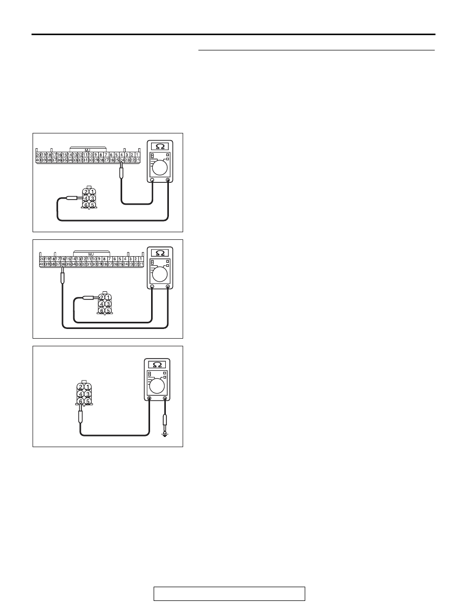
STEP 3. Check the wiring harness between the KOS-ECU 
connector C-05 (terminal Nos. 24, 36) and unlock sensor 
(front door: LH) connector E-18 (terminal Nos. 4, 2), and 
between unlock sensor (front door: LH) connector E-18 
(terminal No. 6) and ground for open circuit.
(1) Disconnect KOS-ECU connector C-05 and unlock sensor 

(front door: LH) connector E-18, and check the wiring 
harness.

(2) Check the wiring harness between KOS-ECU connector 

C-05 (terminal No.24) and unlock sensor (front door: LH) 
connector E-18 (terminal No.4).

OK: Continuity exists (2 

 or less)

(3) Check the wiring harness between KOS-ECU connector 

C-05 (terminal No.36) and unlock sensor (front door: LH) 
connector E-18 (terminal No.2).

OK: Continuity exists (2 

 or less)

(4) Check the wiring harness between unlock sensor (front 

door: LH) connector E-18 (terminal No.6) and ground.

OK: Continuity exists (2 

 or less)

Q: Is the wiring harness between KOS-ECU connector C-05 

(terminal Nos. 24, 36) and unlock sensor (front door: 
LH) connector E-18 (terminal Nos. 4, 2), and between 
unlock sensor (front door: LH) connector E-18 (terminal 
No. 6) and ground in good condition?
YES  : 
Go to Step 4.
NO (KOS-ECU connector C-05 terminal No.24 

 unlock 

sensor (front door: LH) connector E-18 terminal No.4.) : 

Repair the wiring harness between KOS-ECU 
connector C-05 (terminal No.24) and unlock sensor 
(front door: LH) connector E-18 (terminal No.4).

NO (KOS-ECU connector C-05 terminal No.36 

 unlock 

sensor (front door: LH) connector E-18 terminal No.2.) : 

Repair the wiring harness between KOS-ECU 
connector C-05 (terminal No.36) and unlock sensor 
(front door: LH) connector E-18 (terminal No.2).

NO (unlock sensor (front door: LH) connector E-18 
terminal No.6 

 ground.) : Repair the wiring harness 

between unlock sensor (front door: LH) connector 
E-18 (terminal No.6) and ground.

AC709707

Harness side: C-05

GK

Harness side: E-18

AC709707GL

Harness side: C-05

Harness side: E-18

AC209731

Connector E-18 
(harness side)

AC208731CG

DIAGNOSIS

TSB Revision

KEYLESS OPERATION SYSTEM (KOS)

42B-216

STEP 4. Check the wiring harness between the unlock 
sensor (front door: LH) connector E-18 (terminal Nos. 4, 2, 
6) and the ground for short circuit.
(1) Disconnect unlock sensor (front door: LH) connector E-18, 

and check the wiring harness.

(2) Check the wiring harness between unlock sensor (front 

door: LH) connector E-18 (terminal No. 4) and ground

OK: No continuity

(3) Check the wiring harness between unlock sensor (front 

door: LH) connector E-18 (terminal No. 2) and ground

OK: No continuity

(4) Check the wiring harness between unlock sensor (front 

door: LH) connector E-18 (terminal No.6) and ground.

OK: No continuity

Q: Is the wiring harness between unlock sensor (front 

door: LH) connector E-18 (terminal Nos. 4, 2, 6) and the 
ground in good condition?
YES  : 
Go to Step 5.
NO [unlock sensor (front door: LH) connector E-18 
terminal No.4 

 ground.] : Repair the wiring harness 

between unlock sensor (front door: LH) connector 
E-18 (terminal No.4) and ground.

NO [unlock sensor (front door: LH) connector E-18 
terminal No.2 

 ground.] : Repair the wiring harness 

between unlock sensor (front door: LH) connector 
E-18 (terminal No.2) and the ground.

NO [unlock sensor (front door: LH) connector E-18 
terminal No.6 

 ground.] : Repair the wiring harness 

between unlock sensor (front door: LH) connector 
E-18 (terminal No.6) and the ground.

AC709707IR

Harness side: E-18

AC709707IS

Harness side: E-18

AC209731

AC208731CN

Harness side: E-18

DIAGNOSIS

TSB Revision

KEYLESS OPERATION SYSTEM (KOS)

42B-217

STEP 5. KOS communication test
Using scan tool (M.U.T-III), perform the antenna communica-
tion test to check that the exterior transmitter antenna (driver's 
side) communicates normally (Refer to 

P.42B-265

).

Q: Is the check result normal?

YES : Go to Step 6.
NO :  Perform troubleshooting for the diagnostic trouble 

code No. B240A (Refer to 

P.42B-72

).

STEP 6. Check of the troubles
Operate the unlock sensor (front door: LH) and check that the 
door can be locked.
Q: Is the check result normal?

YES : The diagnosis is complete.
NO :  Replace KOS-ECU and register the ID codes (Refer 

to 

P.42B-12

).

Inspection Procedure 11: Front passenger's door lock switch does not work.

CAUTION

Before replacing the ECU, ensure that the power 
supply circuit, the ground circuit and the com-
munication circuit are normal.

AC709309

KOS-ECU

LOCK SWITCH 
(FRONT DOOR: RH)

BLA

CK

BLA

CK

BLA

CK

BLA

CK

ORANGE

YELLO

W

-BLUE

 Lock Switch (Front Door: RH) Circuit

AB

DIAGNOSIS

TSB Revision

KEYLESS OPERATION SYSTEM (KOS)

42B-218

.

TROUBLESHOOTING HINTS

• Malfunction of the exterior transmitter antenna 

assembly (front passenger's side)

• Malfunction of the lock switch (front door: RH)

• Damaged wiring harness and connectors

• Malfunction of the KOS-ECU

DIAGNOSIS

Required Special Tools:

• MB992006: Extra fine probe

• MB991223: Harness set

• MB991958: Scan Tool (M.U.T.-III Sub Assembly)

• MB991824: Vehicles Communication Interface (V.C.I.)

• MB991827: M.U.T.-III USB Cable

• MB991910: M.U.T.-III Main Harness A

AC708950AZ

Connector: C-05

AC708951AX

C-116

C-117 (BR)

Connectors: C-116, C-117

AC608168 AC

Connector: E-06

E-06 (GR)


Content   ..  575  576  577  578   ..