Mitsubishi Evolution X. Manual - part 575


  Index      Mitsubishi     Mitsubishi Evolution X - service repair manual 2008 year


Search            


Content   ..  573  574  575  576   ..


Mitsubishi Evolution X. Manual - part 575


DIAGNOSIS

TSB Revision

KEYLESS OPERATION SYSTEM (KOS)

42B-207

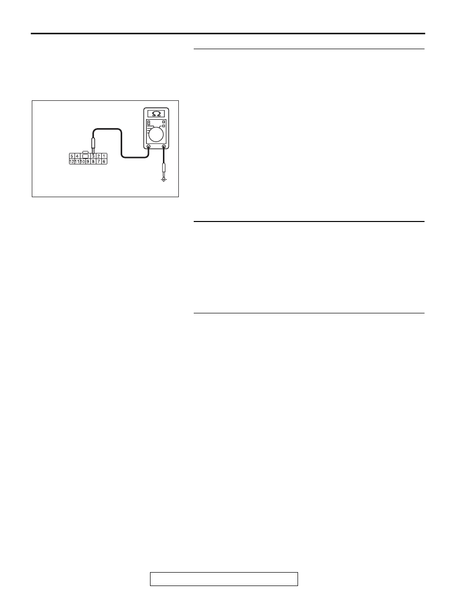
STEP 7. Check the wiring harness between the key 
reminder switch connector C-211 (terminal No. 3) and the 
ground for short circuit.
(1) Disconnect key reminder switch connector C-211, and 

check the wiring harness.

(2) Check the wiring harness between key reminder switch 

connector C-211 (terminal No. 3) and ground

OK: No continuity

Q: Is the wiring harness between key reminder switch 

connector C-211 (terminal No. 3) and the ground in good 
condition?
YES  : 
Go to Step 8.
NO (key reminder switch connector C-211 terminal No.3  
 ground.) : Repair the wiring harness between key 

reminder switch connector C-211 (terminal No. 3) and 
ground.

STEP 8. Check with another registered keyless operation 
key.
Q: Does the IG knob turn? (Is the keyless operation key 

recognised?)
YES : 
Replace the keyless operation key with which the IG 

knob does not turn (no recognition) and register the 
ID codes (Refer to 

P.42B-12

).

NO :  Go to Step 9.

STEP 9. Check of the troubles
Operate the lock switch and check that the door can be locked 
and unlocked. Also, check that the unlock sensor can lock and 
unlock the door.
Q: Is the check result normal?

YES : The diagnosis is complete.
NO :  Replace KOS-ECU and register the ID codes (Refer 

to 

P.42B-12

).

AC709707IW

Harness side: C-211

DIAGNOSIS

TSB Revision

KEYLESS OPERATION SYSTEM (KOS)

42B-208

Inspection Procedure 9: Driver's door lock switch does not work.

CAUTION

Before replacing the ECU, ensure that the power 
supply circuit, the ground circuit and the com-
munication circuit are normal.

.

TROUBLESHOOTING HINTS

• Malfunction of the exterior transmitter antenna 

assembly (driver's side)

• Malfunction of the lock switch (front door: LH)

• Damaged wiring harness and connectors

• Malfunction of the KOS-ECU

AC709307

KOS-ECU

LOCK SWITCH 
(FRONT DOOR: LH)

BLA

CK

BLA

CK

BLA

CK

BLA

CK

GREEN -WHITE

GREEN -WHITE

 Lock Switch (Front Door: LH) Circuit

AB

AC708950BD

C-129 (BR)

C-128

C-05

Connectors: C-05, C-128, C-129

AC608167AQ

Connector: E-17

E-17 (GR)

DIAGNOSIS

TSB Revision

KEYLESS OPERATION SYSTEM (KOS)

42B-209

DIAGNOSIS

Required Special Tools:

• MB992006: Extra fine probe

• MB991223: Harness set

• MB991958: Scan Tool (M.U.T.-III Sub Assembly)

• MB991824: Vehicles Communication Interface (V.C.I.)

• MB991827: M.U.T.-III USB Cable

• MB991910: M.U.T.-III Main Harness A

STEP 1. Using scan tool MB991958, read the diagnostic 
trouble code.

CAUTION

To prevent damage to scan tool MB991958, always turn the 
ignition switch to the "LOCK" (OFF) position before con-
necting or disconnecting scan tool MB991958.
(1) Connect scan tool MB991958. Refer to "How to connect 

scan tool (M.U.T.-III) 

P.42B-10

."

(2) Turn the ignition switch to the "ON" position.
(3) Check whether the KOS-ECU related DTC is set.
(4) Turn the ignition switch to the "LOCK" (OFF) position.
Q: Is the DTC set?

YES : Diagnose the KOS-ECU. Refer to 

P.42B-20

.

NO :  Go to Step 2.

STEP 2. Check KOS-ECU connector C-05 and lock switch 
(front door: LH) connector E-17 for loose, corroded or 
damaged terminals, or terminals pushed back in the 
connector.
Q: Are KOS-ECU connector C-05 and lock switch (front 

door: LH) connector E-17 in good condition?
YES : 
Go to Step 3.
NO :  Repair or replace the damaged component(s). Refer 

to GROUP 00E, Harness Connector Inspection 

P.00E-2

. Check that the driver’s door lock switch 

works normally.

AC608435

Data link connector

MB991827

MB991824

MB991910

AB

DIAGNOSIS

TSB Revision

KEYLESS OPERATION SYSTEM (KOS)

42B-210

STEP 3. Check the lock switch (front door: LH).
(1) Remove the door outside handle base. Refer to GROUP 

42A, Door Handle and Latch 

P.42A-129

.

(2) Check continuity when the lock switch (front door: LH) is 

operated to "ON" or "OFF" position.

Q: Is the lock switch (front door: LH) normal?

YES : Go to Step 4.
NO :  Replace the door outside handle base (front door: 

LH).

Switch position

Terminal number Specified 

condition

ON

− 2

Continuity exists 
(2 

Ω or less)

OFF

− 2

Open circuit

AC506541AB

Lock switch

Door outside
handle base


Content   ..  573  574  575  576   ..