Mitsubishi Evolution X. Manual - part 574


  Index      Mitsubishi     Mitsubishi Evolution X - service repair manual 2008 year


Search            


Content   ..  572  573  574  575   ..


Mitsubishi Evolution X. Manual - part 574


DIAGNOSIS

TSB Revision

KEYLESS OPERATION SYSTEM (KOS)

42B-203

Inspection Procedure 8: No door will be locked or unlocked by operating a lock switch on any door, 
or by touching the unlock sensor.

CAUTION

Before replacing the ECU, ensure that the power 
supply circuit, the ground circuit and the com-
munication circuit are normal.

.

TROUBLESHOOTING HINTS

• Malfunction of the CAN bus lines

• Malfunction of the central door locking system

• Malfunction of the keyless operation key

• Malfunction of the key reminder switch

• Damaged wiring harness and connectors

• Malfunction of the KOS-ECU

• Function setting error or no setting with a custom-

ization

AC609048

KEY
REMINDER
SWITCH

WHEN 
REMOVING 
KEY: ON

ETACS-ECU

RED- WHITE

BLA

CK

BLA

CK

BLA

CK

BLA

CK

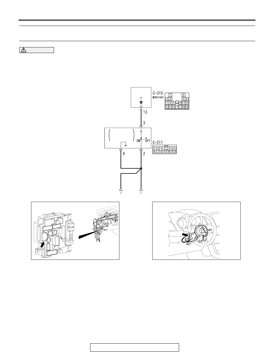
 ETACS-ECU and Key Reminder Switch Circuit

AC

AC708972AU

Connector: C-315

ETACS-ECU

AC708953AC

Connector: C-211

DIAGNOSIS

TSB Revision

KEYLESS OPERATION SYSTEM (KOS)

42B-204

DIAGNOSIS

Required Special Tools:

• MB992006: Extra fine probe

• MB991223: Harness set

• MB991958: Scan Tool (M.U.T.-III Sub Assembly)

• MB991824: Vehicles Communication Interface (V.C.I.)

• MB991827: M.U.T.-III USB Cable

• MB991910: M.U.T.-III Main Harness A

STEP 1. Using scan tool MB991958, read CAN bus 
diagnostic trouble code.

CAUTION

To prevent damage to scan tool MB991958, always turn the 
ignition switch to the "LOCK" (OFF) position before con-
necting or disconnecting scan tool MB991958.
(1) Connect scan tool MB991958. Refer to "How to connect 

scan tool (M.U.T.-III) 

P.42B-10

."

(2) Turn the ignition switch to the "ON" position.
(3) Check whether the CAN bus lines related DTC is set.
(4) Turn the ignition switch to the "LOCK" (OFF) position.
Q: Is the DTC set?

YES : Repair the CAN bus line (Refer to GROUP 54C, CAN 

bus diagnostics table 

P.54C-14

).

NO :  Go to Step 2.

AC608435

Data link connector

MB991827

MB991824

MB991910

AB

DIAGNOSIS

TSB Revision

KEYLESS OPERATION SYSTEM (KOS)

42B-205

STEP 2. Using scan tool MB991958, read the diagnostic 
trouble code.

CAUTION

To prevent damage to scan tool MB991958, always turn the 
ignition switch to the "LOCK" (OFF) position before con-
necting or disconnecting scan tool MB991958.
(1) Connect scan tool MB991958. Refer to "How to connect 

scan tool (M.U.T.-III) 

P.42B-10

."

(2) Turn the ignition switch to the "ON" position.
(3) Check whether the KOS-ECU related DTC is set.
(4) Turn the ignition switch to the "LOCK" (OFF) position.
Q: Is the DTC set?

YES : Diagnose the KOS-ECU. Refer to 

P.42B-20

.

NO :  Go to Step 3.

STEP 3. Check the central door locking operation
Check that the central door locking system works normally.
Q: Is the check result normal?

YES : Go to Step 4.
NO :  Perform troubleshooting for the central door locking 

system (Refer to GROUP 42A, Door 

− 

Troubleshooting 

P.42A-30

).

STEP 4. Check the customize function.
Check that either of the followings other than "ENG strt enable" 
or "Both disabled" are set for "KOS feature" with the customiza-
tion function.

• Both enable

• Door Entry enable

Q: Is the check result normal?

YES : Go to Step 5.
NO :  Set either of the followings other than "ENG strt 

enable" or "Both disabled" for "KOS feature" with the 
customization function (Refer to 

P.42B-276

).

AC608435

Data link connector

MB991827

MB991824

MB991910

AB

DIAGNOSIS

TSB Revision

KEYLESS OPERATION SYSTEM (KOS)

42B-206

STEP 5. Key reminder switch check
(1) Disconnect the C-315 ETACS-ECU connector.
(2) Measure the resistance at the harness-side connector with 

the ignition key removed from the ignition key cylinder.

(3) Check the continuity between the C-315 ETACS-ECU 

connector terminal No. 13 and the ground.

OK: Continuity exists (2 

 or less)

Q: Is the check result normal?

YES : Go to Step 8.
NO :  Go to Step 6.

STEP 6. Check the wiring harness between the key 
reminder switch connector C-211 (terminal No. 3) and 
ETACS-ECU connector C-315 (terminal No. 13) for open 
circuit.
(1) Disconnect key reminder switch connector C-211 and 

ETACS-ECU connector C-315, and check the wiring 
harness.

(2) Check the wiring harness between key reminder switch 

connector C-211 (terminal No. 3) and ETACS-ECU 
connector C-315 (terminal No. 13).

OK: Continuity exists (2 

 or less)

Q: Is the wiring harness between key reminder switch 

connector C-211 (terminal No. 3) and ETACS-ECU 
connector C-315 (terminal No. 13) in good condition?
YES  : 
Go to Step 7.
NO (key reminder switch connector C-211 terminal No.3 
 ETACS-ECU connector C-315 terminal No.13.) : Repair 

the wiring harness between key reminder switch 
connector C-211 (terminal No. 3) and ETACS-ECU 
connector C-315 (terminal No. 13).

AC209731

Connector C-315
(harness side)

AC208731BP

AC709707

Harness side: C-315

IV

Harness side: C-211


Content   ..  572  573  574  575   ..