Mitsubishi Evolution X. Manual - part 573
DIAGNOSIS
TSB Revision
KEYLESS OPERATION SYSTEM (KOS)
42B-199
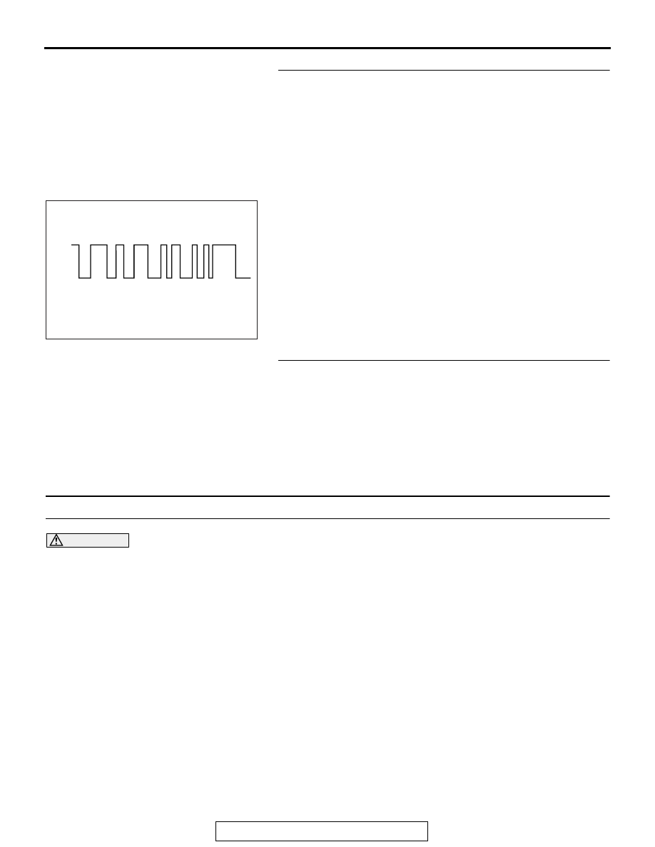
STEP 12. Using the oscilloscope, check the waveform at
receiver antenna module connector D-14 and ground by
backprobing.
(1) Do not disconnect the receiver antenna assembly
connector D-14.
(2) Connect an oscilloscope to receiver antenna assembly
connector D-14 terminal No. 12 and ground by
backprobing.
(3) Turn the ignition switch to the "LOCK" (OFF) position.
•
Check the waveform.
Q: Is the waveform normal?
YES : Go to Step 13.
NO : Replace the receiver antenna assembly.
STEP 13. Check of the troubles.
Check that the IG turns (keyless operation is recognised).
Q: Dose the IG knob will not turn (keyless operation is not
recognized) in good condition?
YES : The procedure is complete.
NO : Replace KOS-ECU and register the ID codes. (Refer
to
Inspection Procedure 6: The engine will not start with KOS (IG knob operates normally).
CAUTION
Before replacing the ECU, ensure that the com-
munication circuit is normal.
.
TROUBLESHOOTING HINTS
• The CAN bus line is defective.
• Malfunction of the MFI system
• Function setting error or no setting with customi-
zation
• VIN not written or unmatched
DIAGNOSIS
Required Special Tools:
• MB991958: Scan Tool (M.U.T.-III Sub Assembly)
• MB991824: Vehicles Communication Interface (V.C.I.)
• MB991827: M.U.T.-III USB Cable
• MB991910: M.U.T.-III Main Harness A
AC602456
0V
5.0V
AC
Normal waveform