Mitsubishi Evolution X. Manual - part 578


  Index      Mitsubishi     Mitsubishi Evolution X - service repair manual 2008 year


Search            


Content   ..  576  577  578  579   ..


Mitsubishi Evolution X. Manual - part 578


DIAGNOSIS

TSB Revision

KEYLESS OPERATION SYSTEM (KOS)

42B-219

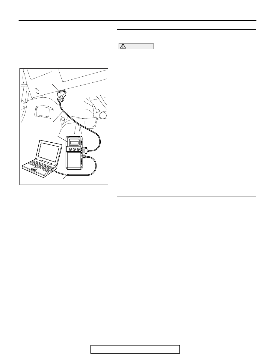
STEP 1. Using scan tool MB991958, read the diagnostic 
trouble code.

CAUTION

To prevent damage to scan tool MB991958, always turn the 
ignition switch to the "LOCK" (OFF) position before con-
necting or disconnecting scan tool MB991958.
(1) Connect scan tool MB991958. Refer to "How to connect 

scan tool (M.U.T.-III) 

P.42B-10

."

(2) Turn the ignition switch to the "ON" position.
(3) Check whether the KOS-ECU related DTC is set.
(4) Turn the ignition switch to the "LOCK" (OFF) position.
Q: Is the DTC set?

YES : Diagnose the KOS-ECU. Refer to 

P.42B-20

.

NO :  Go to Step 2.

STEP 2. Check KOS-ECU connector C-05 and lock switch 
(front door: RH) connector E-06 for loose, corroded or 
damaged terminals, or terminals pushed back in the 
connector.
Q: Are KOS-ECU connector C-05 and lock switch (front 

door: RH) connector E-06 in good condition?
YES : 
Go to Step 3.
NO :  Repair or replace the damaged component(s). Refer 

to GROUP 00E, Harness Connector Inspection 

P.00E-2

. Check that the passenger’s door lock switch 

works normally.

AC608435

Data link connector

MB991827

MB991824

MB991910

AB

DIAGNOSIS

TSB Revision

KEYLESS OPERATION SYSTEM (KOS)

42B-220

STEP 3. Check the lock switch (front door: RH).
(1) Remove the door outside handle base. Refer to GROUP 

42A, Door Handle and Latch 

P.42A-129

.

(2) Check continuity when the lock switch (front door: RH) is 

operated to "ON" or "OFF" position.

Q: Is the lock switch (front door: RH) normal?

YES : Go to Step 4.
NO :  Replace the door outside handle base (front door: 

RH).

Switch position

Terminal number Specified 

condition

ON

− 2

Continuity exists 
(2 

Ω or less)

OFF

− 2

Open circuit

AC506541AB

Lock switch

Door outside
handle base

DIAGNOSIS

TSB Revision

KEYLESS OPERATION SYSTEM (KOS)

42B-221

STEP 4. Check the wiring harness between the KOS-ECU 
connector C-05 (terminal No. 23) and lock switch (front 
door: RH) connector E-06 (terminal No. 1), and between 
lock switch (front door: RH) connector E-06 (terminal No. 
2) and ground for open circuit.
(1) Disconnect KOS-ECU connector C-05 and lock switch 

(front door: RH) connector E-06, and check the wiring 
harness.

(2) Check the wiring harness between KOS-ECU connector 

C-05 (terminal No.23) and lock switch (front door: RH) 
connector E-06 (terminal No.1).

OK: Continuity exists (2 

 or less)

(3) Check the wiring harness between lock switch (front door: 

RH) connector E-06 (terminal No.2) and ground.

OK: Continuity exists (2 

 or less)

Q: Is the wiring harness between KOS-ECU connector C-05 

(terminal No. 23) and lock switch (front door: RH) 
connector E-06 (terminal No. 1), and between lock 
switch (front door: RH) connector E-06 (terminal No. 2) 
and ground in good condition?
YES  : 
Go to Step 5.
NO (KOS-ECU connector C-05 terminal No.23 

 lock 

switch (front door: RH) connector E-06 terminal No.1.) : 

Repair the wiring harness between KOS-ECU 
connector C-05 (terminal No.23) and lock switch 
(front door: RH) connector E-06 (terminal No.1).

NO (lock switch (front door: RH) connector E-06 
terminal No.2 

 ground.) : Repair the wiring harness 

between lock switch (front door: RH) connector E-06 
(terminal No.2) and ground.

AC709707 GU

Harness side: E-06

Harness side: C-05

AC209731

Connector E-06 
(harness side)

AC208731CH

DIAGNOSIS

TSB Revision

KEYLESS OPERATION SYSTEM (KOS)

42B-222

STEP 5. Check the wiring harness between the lock switch 
(front door: RH) connector E-06 (terminal Nos. 1, 2) and the 
ground for short circuit.
(1) Disconnect lock switch (front door: RH) connector E-06, 

and check the wiring harness.

(2) Check the wiring harness between lock switch (front door: 

RH) connector E-06 (terminal No. 1) and ground

OK: No continuity

(3) Check the wiring harness between lock switch (front door: 

RH) connector E-06 (terminal No. 2) and ground

OK: No continuity

Q: Is the wiring harness between lock switch (front door: 

RH) connector E-06 (terminal Nos. 1, 2) and the ground 
in good condition?
YES  : 
Go to Step 6.
NO [lock switch (front door: RH) connector E-06 
terminal No.1 

 ground.] : Repair the wiring harness 

between lock switch (front door: RH) connector E-06 
(terminal No.1) and ground.

NO [lock switch (front door: RH) connector E-06 
terminal No.2 

 ground.] : Repair the wiring harness 

between lock switch (front door: RH) connector E-06 
(terminal No.2) and the ground.

STEP 6. KOS communication test
Using scan tool (M.U.T-III), perform the antenna communica-
tion test to check that the exterior transmitter antenna (passen-
ger's side) communicates normally (Refer to 

P.42B-265

).

Q: Is the check result normal?

YES : Go to Step 7.
NO :  Perform troubleshooting for the diagnostic trouble 

code No. B240B (Refer to 

P.42B-78

).

STEP 7. Check of the troubles
Operate the lock switch (front door: RH) to check that the door 
can be locked. 
Q: Is the check result normal?

YES : The diagnosis is complete.
NO :  Replace KOS-ECU and register the ID codes (Refer 

to 

P.42B-12

).

AC209731

AC208731CO

Harness side: E-06

AC209731

AC208731CP

Harness side: E-06


Content   ..  576  577  578  579   ..