Mitsubishi Evolution X. Manual - part 498
DOOR
TSB Revision
BODY
42A-95
.
CIRCUIT OPERATION
When you operate each power window switch for
front or rear passengers (incorporated in the power
window main switch), the corresponding power win-
dow motor operates, opening or closing each power
window.
.
TECHNICAL DESCRIPTION (COMMENT)
If the corresponding power window opens and closes
normally when each power window sub-switch is
operated, the power window main switch may be
defective.
.
TROUBLESHOOTING HINT
• The power window main switch may be defective
• The front power window sub switch may be
defective
• The rear power window sub switches may be
defective
• The ETACS-ECU may be defective
• The wiring harness or connectors may have
loose, corroded, or damaged terminals, or termi-
nals pushed back in the connector
DIAGNOSTIC PROCEDURE
Required Special Tools:
• MB992006: Extra fine probe
• MB991223: Harness set
• MB991958: Scan Tool (M.U.T.-III Sub Assembly)
• MB991824: Vehicles Communication Interface (V.C.I.)
• MB991827: M.U.T.-III USB Cable
• MB991910: M.U.T.-III Main Harness A (Vehicles with
CAN communication system)
STEP 1. Check the power window main switch.
Check that the driver's power window works by means of the
power window main switch.
Q: Is the check result normal?
YES : Go to Step 2.
NO : Refer to inspection procedure 2 "Driver's power
window does not work by means of the power window
main switch
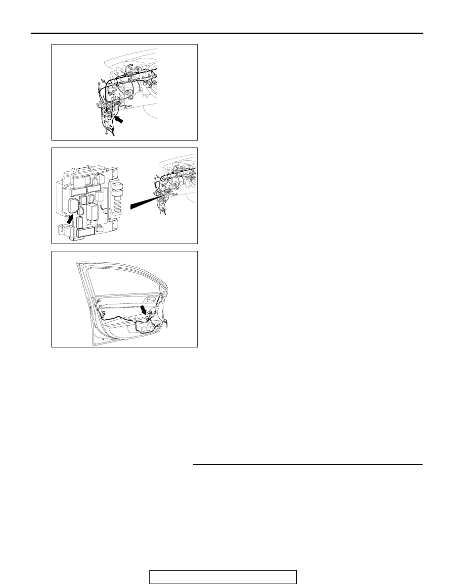
AC708950AS
Connector: C-128
AC708972AU
Connector: C-315
ETACS-ECU
AC608167AM
Connector: E-15