Mitsubishi Evolution X. Manual - part 496


  Index      Mitsubishi     Mitsubishi Evolution X - service repair manual 2008 year


Search            


Content   ..  494  495  496  497   ..


Mitsubishi Evolution X. Manual - part 496


DOOR

TSB Revision

BODY

42A-87

STEP 15. Check the rear power window motor (LH).
(1) Remove the rear power window regulator (LH). Refer to 

Door Glass and Regulator 

P.42A-124

.

(2) Connect a battery to the motor terminal, and check that the 

motor runs freely.

Q: Is the rear power window motor (LH) normal?

YES : Go to Step 16.
NO :  Replace the rear power window regulator (LH). When 

the rear power window sub switch (LH) is operated, 
the rear power window (LH) should raise and lower 
normally.

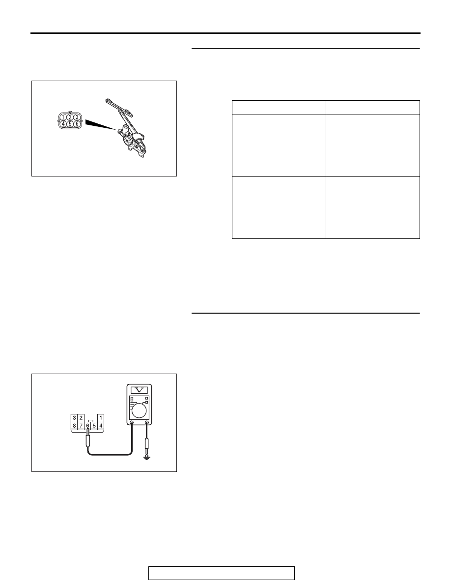
STEP 16. Check the battery power supply circuit to the rear 
power window sub switch (LH). Measure the voltage at rear 
power window sub switch (LH) connector E-24.
(1) Disconnect rear power window sub switch (LH) connector 

E-24 and measure the voltage available at the wiring 
harness side of the connector.

(2) Measure the voltage between terminal 6 and ground.

• The voltage should measure approximately 12 volts 

(battery positive voltage).

Q: Is the measured voltage approximately 12 volts (battery 

positive voltage)?
YES : 
Go to Step 19.
NO :  Go to Step 17.

Battery connection

Slider position

• Connect terminal 4 to 

the negative battery 
terminal

• Connect terminal 1 to 

the positive battery 
terminal

UP

• Connect terminal 1 to 

the negative battery 
terminal

• Connect terminal 4 to 

the positive battery 
terminal

DOWN

AC609373AB

AC208730BQ

Connector E-24 
(harness side)

DOOR

TSB Revision

BODY

42A-88

STEP 17. Check ETACS-ECU connector C-311 for loose, 
corroded or damaged terminals, or terminals pushed back 
in the connector.
Q: Is ETACS-ECU connector C-311 in good condition?

YES : Go to Step 18.
NO :  Repair or replace the damaged component(s). Refer 

to GROUP 00E, Harness Connector Inspection 

P.00E-2

. When the rear power window sub switch 

(LH) is operated, the rear power window (LH) should 
raise and lower normally.

STEP 18. Check the wiring harness between ETACS-ECU 
connector C-311 (terminal No. 12) and rear power window 
sub switch (LH) connector E-24 (terminal No. 6).
NOTE: Also check joint connector (5) D-27, intermediate con-
nector D-24. If joint connector (5) D-27, intermediate connector 
D-24 is damaged, repair or replace the connector as described 
in GROUP 00E, Harness Connector Inspection 

P.00E-2

.

Q: Is the wiring harness between ETACS-ECU connector 

C-311 (terminal No. 12) and rear power window sub 
switch (LH) connector E-24 (terminal No. 6) in good 
condition?
YES : 
No action is necessary and testing is complete.
NO :  The wiring harness may be damaged or the 

connector(s) may have loose, corroded or damaged 
terminals, or terminals pushed back in the connector. 
Repair the wiring harness as necessary. When the 
rear power window sub switch (LH) is operated, the 
rear power window (LH) should raise and lower 
normally.

STEP 19. Check the ground circuit to the rear power 
window sub switch (LH). Measure the resistance at rear 
power window sub switch (LH) connector E-24.
(1) Disconnect rear power window sub switch (LH) connector 

E-24 and measure the resistance available at the wiring 
harness side of the connector.

(2) Measure the resistance value between terminal 5 and 

ground, and also between terminal 8 and ground.

• The resistance should be 2 ohms or less.

Q: Is the measured resistance 2 ohms or less?

YES : Go to Step 21.
NO :  Go to Step 20.

AC209731

AC208731CB

Connector E-24 
(harness side)

DOOR

TSB Revision

BODY

42A-89

STEP 20. Check the wiring harness between power 
window main switch connector E-15 (terminals Nos. 18 
and 19) and rear power window sub switch (LH) connector 
E-24 (terminals Nos. 5 and 8).
NOTE: Also check intermediate connectors C-42, C-128 and 
D-24. If intermediate connectors C-42, C-128 or D-24 is dam-
aged, repair or replace the damaged component(s) as 
described in GROUP 00E, Harness Connector Inspection 

P.00E-2

.

Q: Is the wiring harness between power window main 

switch connector E-15 (terminals Nos. 18 and 19) and 
rear power window sub switch (LH) connector E-24 
(terminals Nos. 5 and 8) in good condition?
YES : 
Replace the power window main switch. When the 

rear power window sub switch (LH) is operated, the 
rear power window (LH) should raise and lower 
normally.

NO :  The wiring harness may be damaged or the 

connector(s) may have loose, corroded or damaged 
terminals, or terminals pushed back in the connector. 
Repair the wiring harness as necessary. When the 
rear power window sub switch (LH) is operated, the 
rear power window (LH) should raise and lower 
normally.

STEP 21. Check the wiring harness between rear power 
window sub switch (LH) connector E-24 (terminals Nos. 4 
and 7) and rear power window motor (LH) connector E-25 
(terminals Nos. 4 and 1).
Q: Is the wiring harness between rear power window sub 

switch (LH) connector E-24 (terminals Nos. 4 and 7) and 
rear power window motor (LH) connector E-25 
(terminals Nos. 4 and 1) in good condition?
YES : 
Replace the power window main switch. When the 

rear power window sub switch (LH) is operated, the 
rear power window (LH) should raise and lower 
normally.

NO :  The wiring harness may be damaged or the 

connector(s) may have loose, corroded or damaged 
terminals, or terminals pushed back in the connector. 
Repair the wiring harness as necessary. When the 
rear power window sub switch (LH) is operated, the 
rear power window (LH) should raise and lower 
normally.

DOOR

TSB Revision

BODY

42A-90

STEP 22. Check rear power window sub switch (RH) 
connector E-21 and rear power window motor (RH) 
connector E-20 for loose, corroded or damaged terminals, 
or terminals pushed back in the connector.
Q: Are rear power window sub switch (RH) connector E-21 

and rear power window motor (RH) connector E-20 in 
good condition?
YES : 
Go to Step 23.
NO :  Repair or replace the damaged component(s). Refer 

to GROUP 00E, Harness Connector Inspection 

P.00E-2

. When the rear power window sub switch 

(RH) is operated, the rear power window (RH) should 
raise and lower normally.

STEP 23. Check the rear power window sub switch (RH) for 
continuity.
(1) Remove the rear power window sub switch (RH). Refer to 

Door Glass and Regulator 

P.42A-124

.

(2) Check continuity when the rear power window sub switch 

(RH) is operated to "UP" or "DOWN" position.

Q: Is the rear power window sub switch (RH) normal?

YES : Go to Step 24.
NO :  Replace the rear power window sub switch (RH). 

When the rear power window sub switch (RH) is 
operated, the rear power window (RH) should raise 
and lower normally.

Switch 
position

Tester 
connection

Specified 
condition

UP

− 5, 6 − 7

Continuity 
exists (2 

Ω or 

less)

OFF

− 5, 7 − 8

Continuity 
exists (2 

Ω or 

less)

DOWN

− 6, 7 − 8

Continuity 
exists (2 

Ω or 

less)

AC310098

8

3

4 5

1

2

6 7

AB


Content   ..  494  495  496  497   ..