Mitsubishi Evolution X. Manual - part 470
KEY INTERLOCK AND SHIFT LOCK MECHANISMS
TSB Revision
TWIN CLUTCH- SPORTRONIC SHIFT TRANSMISSION (TC-SST)
22C-337
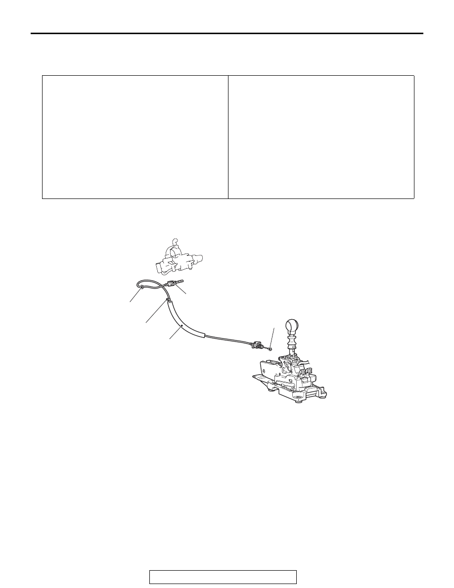
KEY INTERLOCK AND SHIFT LOCK MECHANISMS
REMOVAL AND INSTALLATION
M1225009800017
Pre-removal Operation
• Floor console bracket (A) and floor console side cover
removal (Refer to GROUP 52A
− Floor Console Assembly
.)
• Instrument panel cover lower removal <Leather combina-
tion interior package (Vehicles without side air bag)>
(Refer to GROUP 52A
− Instrument Lower Panel
.)
• Steering column lower cover removal (Refer to GROUP
37
− Steering Shaft
• Foot duct (driver's side) removal (Refer to GROUP 55 −
Post-installation Operation
• Foot duct (driver's side) installation (Refer to GROUP 55 −
• Steering column lower cover installation (Refer to GROUP
37
− Steering Shaft
• Instrument panel cover lower installation <Leather combi-
nation interior package (Vehicles without side air bag)>
(Refer to GROUP 52A
− Instrument Lower Panel
.)
• Floor console bracket (A) and floor console side cover
installation (Refer to GROUP 52A
− Floor Console
Assembly
.)
• Key interlock mechanism check (Refer to
• Shift lock mechanism check (Refer to
.)
• Shift lever operation check (Refer to
AC705527
AC709660AB
2
1
5
3
4
Removal steps
1.
Band clip
2.
Wiring harness clip
>>
B
3.
Key interlock cable
connection (shift lever side)
<<
A
>>
>>
A
4.
Key interlock cable
connection (steering side)
5.
Key interlock cable
Removal steps