Mitsubishi Evolution X. Manual - part 468


  Index      Mitsubishi     Mitsubishi Evolution X - service repair manual 2008 year


Search            


Content   ..  466  467  468  469   ..


Mitsubishi Evolution X. Manual - part 468


ON-VEHICLE SERVICE

TSB Revision

TWIN CLUTCH- SPORTRONIC SHIFT TRANSMISSION (TC-SST)

22C-329

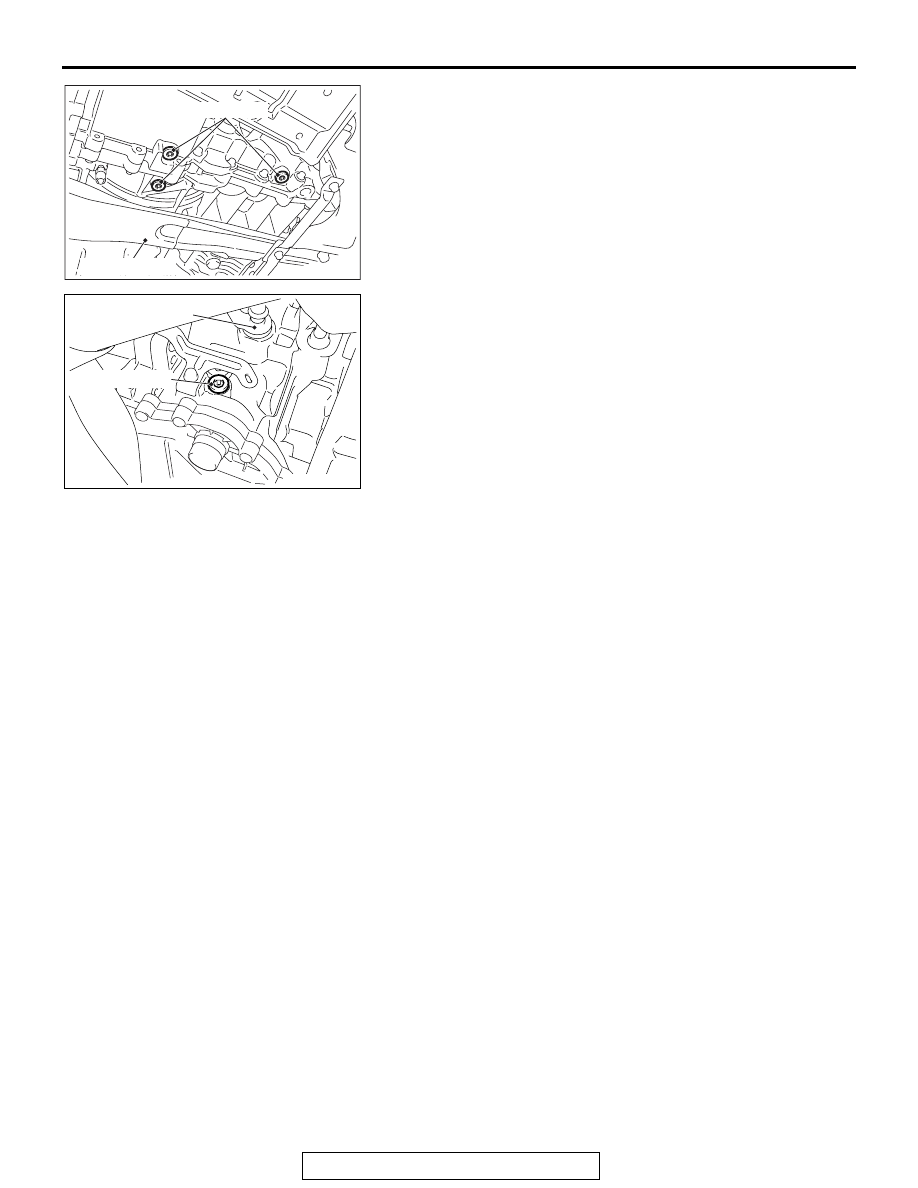
2. Remove the oil drain plug to drain the oil.

NOTE: Because the oil in the oil cooler and oil filter cannot 
be drained, the amount of drained oil will be approximately 
5.5 dm

3

.

3. Tighten the oil drain plug to the specified torque.

Tightening torque: 25 N

⋅ m (19 ft-lb)

4. Remove the air cleaner element, air cleaner intake duct, and 

air cleaner body. (Refer to GROUP 15 

− Air Cleaner 

P.15-10

.)

5. Remove the oil filler plug, then fill the oil.

Brand name: Mitsubishi genuine Dia-Queen SSTF-I
Filling amount: Approximately 5.5 dm

3

 (approximately 

5.8 quarts)

6. Tighten the oil filler plug to the specified torque.

Tightening torque: 25 N

⋅ m (19 ft-lb)

7. Install the air cleaner element, air cleaner intake duct, and 

air cleaner body. (Refer to GROUP 15 

− Air Cleaner 

P.15-10

.)

8. Start the engine, then let it idle for 1 to 2 minutes.
9. Move the shift lever to every position, and then move it to 

the P or N range.

10.Stop the engine, then perform Steps 2 to 5 again.
11.Check the oil level and oil fouling. (Refer to 

P.22C-328

.) If 

fouling is found, repeat Steps 2 to 5 until the fouling is 
eliminated.

12.Install the engine compartment under cover front B 

assembly. (Refer to GROUP 51 

− Under Cover 

P.51-16

.)

TRANSFER OIL CHECK

M1225008200012

Refer to GROUP 22A 

 On-vehicle Service 

P.22A-117

.

TRANSFER OIL CHANGE

M1225008300019

Refer to GROUP 22A 

 On-vehicle Service 

P.22A-117

.

AC704517AC

Oil drain plug

Centermember

AC704813AC

Oil filler plug

Transmission control
lever

ON-VEHICLE SERVICE

TSB Revision

TWIN CLUTCH- SPORTRONIC SHIFT TRANSMISSION (TC-SST)

22C-330

SHIFT LEVER OPERATION CHECK

M1225008400016

1. Check that the engine starts when the shift lever is in the N 

or P range, and that the engine does not start in other 
ranges.

2. Start the engine, and release the parking brake. Then, check 

that the vehicle travels forward when the shift lever is in the 
D range or the mode is set to the sport mode, and that the 
vehicle travels backward when the shift lever is set in the R 
range.

3. Stop the engine.
4. Turn ON the ignition switch, and move the shift lever from 

the P to R range. Check that the back-up light becomes on 
and the tone alarm sounds at this time.
NOTE: Because the misoperation preventive device is 
equipped, the shift lever cannot be moved out of the P posi-
tion unless the ignition switch is turned to the position other 
than LOCK (OFF) and the brake pedal is depressed.

KEY INTERLOCK MECHANISM CHECK

M1225008500013

1. Perform the following checks.

2. If there is a problem with above operations, install the key 

interlock cable according to the procedure below. (Automatic 
adjustment)

(1) Disconnect the key interlock cable connection (shift lever 

side).(Refer to 

P.22C-337

.)

CAUTION

Leave the ignition switch in the LOCK (OFF) position until 
the key interlock cable installation is completed.

(2) Move the shift lever to the P position, and turn the ignition 

switch to the LOCK (OFF) position.

AC711471

+

|

P

R

N

D

: The selector lever moves when the brake 
  pedal is depressed and the pull-ring is pulled
  in with the ignition key in any position other
  than the "LOCK" (OFF) position.

: The selector lever moves without pulling the 
  pull-ring.

: The selector lever moves when the pull-ring
  is pulled.

AB

Inspectio

procedur
e

Check conditions

Items to be checked (Normal status)

1

Brake pedal: 
Depressed

Ignition switch position: 
LOCK (OFF) or ACC

The shift lever cannot be moved out of the P 
position.

2

Ignition switch position: 
ON

The shift lever can be moved from the P position 
to other positions smoothly.

3

Selector lever position: Other than P

The ignition switch cannot be turned to the 
LOCK (OFF) position.

4

Selector lever position: P

The ignition switch can be turned to the LOCK 
(OFF) position smoothly.

ON-VEHICLE SERVICE

TSB Revision

TWIN CLUTCH- SPORTRONIC SHIFT TRANSMISSION (TC-SST)

22C-331

(3) Install the tip of key interlock cable to the lock cam of shift 

lever assembly, using a caution not to twist the inner 
cable.

(4) Install the adjuster case with its lock guide pulled up 

(unlocked).

(5) Firmly push down the lock guide to lock it.

NOTE: The lock position of the key interlock cable is 
automatically adjusted by a spring.

AC707937

AC707782

AD

Inner cable

Key interlock cable

A

Spring

Lock

Key interlock cable

Lock guide

Lock guide

View A

Lock cam

Unlock

ON-VEHICLE SERVICE

TSB Revision

TWIN CLUTCH- SPORTRONIC SHIFT TRANSMISSION (TC-SST)

22C-332

SHIFT LOCK MECHANISM CHECK

M1225008600010

SYSTEM CHECK

COMPONENTS CHECK

1. Troubleshoot the shift lever.
2. Remove the shift lever assembly. Then, check that there is 

no damage to each part, and that the shift lever can be 
moved to each position.(Refer to 

P.22C-334

.)

3. After performing the check above, if an abnormality is found, 

replace the shift lever assembly.

FLUID CHECK

M1225008700017

Refer to GROUP 27 

− On-vehicle Service 

P.27-29

.

BLEEDING

M1225008800014

Refer to GROUP 22A 

 On-vehicle Service 

P.22A-118

.

Inspe
ction 
proc
edur
e

Check conditions

Items to be checked 
(Normal status)

Possible cause of 
abnormality

1

Release the 
brake pedal.

Ignition switch 
position: LOCK (OFF) 
or ACC

The shift lever cannot be 
moved out of the P 
position.

• Shift lever assembly 

abnormality (seizure, 
damage, or others)

• Electrical circuit 

abnormality (short circuit in 
solenoid or wiring harness)

• Key interlock mechanism 

abnormality

2

Depress the 
brake pedal.

• Shift lever assembly 

abnormality (seizure, 
damage, or others)

• Key interlock mechanism 

abnormality

3

Release the 
brake pedal.

Ignition switch 
position: ON

• Shift lever assembly 

abnormality (seizure, 
damage, or others)

• Electrical circuit 

abnormality (short circuit in 
solenoid or wiring harness)

4

Depress the 
brake pedal.

The shift lever can be 
moved from the P 
position to other positions 
smoothly.

• Shift lever assembly 

abnormality (seizure, 
damage, or others)

• Electrical circuit 

abnormality (open circuit in 
solenoid or wiring harness)


Content   ..  466  467  468  469   ..