Mitsubishi Evolution X. Manual - part 376


  Index      Mitsubishi     Mitsubishi Evolution X - service repair manual 2008 year


Search            


Content   ..  374  375  376  377   ..


Mitsubishi Evolution X. Manual - part 376


TRANSAXLE

TSB Revision

MANUAL TRANSAXLE OVERHAUL

22B-17

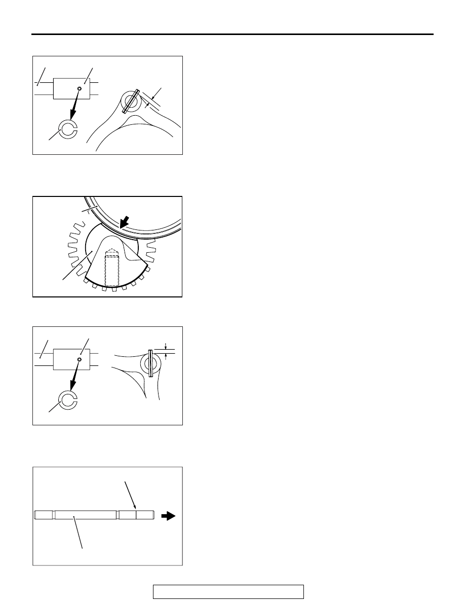
>>B<< SPRING PIN INSTALLATION

AK703408

2.5 mm
(0.0984 inch)

AC

Shift rail

Shift fork

Spring pin

Install the spring pin to the shift rail so that the slit of the spring 
pin aligns with the center axis of the rail as shown.

.

>>C<< REVERSE IDLER GEAR ASSEMBLY 
INSTALLATION

AK703681

Reverse idler
gear assembly

AC

1st-2nd speed
synchronizer sleeve

Install the reverse idler gear assembly so that the notch of the 
reverse idler gear shaft and 1st-2nd speed synchronizer sleeve 
meet at the illustrated position.

.

>>D<< SPRING PIN INSTALLATION

AK703409

2.5 mm
(0.0984 inch)

AC

Shift rail

Shift fork

Spring pin

Install the spring pin to the shift rail so that the slit of the spring 
pin aligns with the center axis of the rail as shown.

.

>>E<< 5TH-REVERSE SPEED SHIFT RALL 
INSTALLATION

AK703410AC

Identification groove

Installation
direction

5th-reverse speed shift rail

Install the 5th-reverse speed shift rail, with its identification 
groove to the clutch housing side.

.

TRANSAXLE

TSB Revision

MANUAL TRANSAXLE OVERHAUL

22B-18

>>F<< REVERSE SHIFT LEVER INSTALLATION

AK703326 AC

Addition mark

Install the reverse shift lever so that its identification mark is 
located at the illustrated position.

.

>>G<< TRANSAXLE CASE INSTALLATION

AK703818AD

Apply a bead (approximately 2 mm (0.0787 inch) thick) of spec-
ified sealant to the transaxle case as shown.

Specified sealant:
Mitsubishi Part No. MD997740 or equivalent

.

>>H<< CONTROL HOUSING INSTALLATION

AK703819AC

Apply a bead (approximately 3.5 mm (0.1378 inch) thick) of 
specified sealant to the control housing as shown.

Specified sealant:
Mitsubishi Part No. MD997740 or equivalent

.

>>I<< BACK-UP LIGHT SWITCH / 1ST-2ND SPEED 
RAIL SWITCH INSTALLATION

AK703332

AC

Back-up light switch

Control shaft

1st-2nd speed
rail switch

Install the back-up light switch and 1st-2nd speed rail switch at 
the illustrated positions.

.

TRANSAXLE

TSB Revision

MANUAL TRANSAXLE OVERHAUL

22B-19

>>J<< SHIFT CABLE BRACKET INSTALLATION

AK703153AC

139 - 141 mm

(5.4724 - 5.5512 inch)

Control

shaft

Shift cable

bracket

1. Install the shift cable bracket loosely.
2. Put the control shaft into neutral.
3. Position the shift cable bracket so that the distance between 

the control shaft and shift cable bracket is within the 
standard value. Then fix the bracket securely.

Standard value: 139 

 141 mm (5.48  5.55 inch)

AK703154AC

139.2 - 140.8 mm

(5.4803 - 5.433 inch)

Select lever bracket

Select lever

Shift cable

bracket

4. Install the select lever bracket loosely.
5. Put the select lever into the 3rd-4th speed position.
6. Position the select lever bracket so that the distance 

between the select lever and shift cable bracket is within the 
standard value. Then fix the bracket securely.

Standard value: 139.2 

 140.8 mm (5.481  5.543 inch)

INSPECTION

M1222016600049

.

BACKUP LIGHT SWITCH / 1-2 speed rall switch

AK201630

Check for continuity between terminals.

Switch Condition

Continuity

Pressed

Open

Released

Conductive

TRANSAXLE ADJUSTMENT

M1222013800129

ADJUSTMENT BEFORE ASSEMBLY

.

SPACER SELECTION FOR INPUT SHAFT PRE-
LOAD / OUTPUT SHAFT PRELOAD / CENTER DIF-
FERENTIAL PRELOAD ADJUSTMENT

<Measurement using solder>

• If soft solder is not available, select the spacer in accor-

dance with Plastigage method.

• If the spacer appropriate for the standard value cannot be 

selected using soft solder, select the spacer in accordance 
with Plastigage method.

AK703323

TRANSAXLE

TSB Revision

MANUAL TRANSAXLE OVERHAUL

22B-20

1. Install the input shaft, output shaft and center differential as 

a set to the clutch housing.

AK703327

AC

Solders

AK703329

AC

Solders

Solders

2. Put a piece of solder [1.6 mm (0.06 in) diameter, 10 mm 

(0.39 in) long] on the transaxle case at the positions shown 
in the illustration.

3. Install the bearing outer races on the pieces of solder.
4. Install the clutch housing to the transaxle case and tighten 

the bolts to the specified torque.

5. Remove the clutch housing, then remove the bearing outer 

races and take out crushed pieces of solder.
NOTE: If the pieces of solder have not crushed, use thicker 
solders and repeat steps 2 to 3.

6. Measure the thickness of crushed solder with a micrometer, 

select the spacers that provide the standard preload values 
and install them.

• Input shaft

Input shaft preload

Spacer thickness: [T + 0.10 mm (0.0039 inch)] 

 [T + 

0.17 mm (0.0067 inch)]
T: Thickness of crushed solder mm (inch)

Standard value: 0.10 

 0.17 mm (0.0039  0.0067 inch)

• Output shaft

Output shaft preload

Spacer thickness: [T + 0.15 mm (0.0059 inch)] 

 [T + 

0.21 mm (0.0083 inch)]
T: Thickness of crushed solder mm (inch)

Standard value: 0.15 

 0.21 mm (0.0059  0.0083 inch)

• Center differential

Center differential preload

Spacer thickness: [T + 0.06 (0.0024 inch)] 

 [T + 0.12 

mm (0.0047 inch)]
T: Thickness of crushed solder mm (inch)

Standard value: 0.06 

 0.12 mm (0.0024  0.0047 inch)

.


Content   ..  374  375  376  377   ..