Mitsubishi Evolution X. Manual - part 275


  Index      Mitsubishi     Mitsubishi Evolution X - service repair manual 2008 year


Search            


Content   ..  273  274  275  276   ..


Mitsubishi Evolution X. Manual - part 275


MULTIPORT FUEL INJECTION (MFI) DIAGNOSIS

TSB Revision

MULTIPORT FUEL INJECTION (MFI)

13A-77

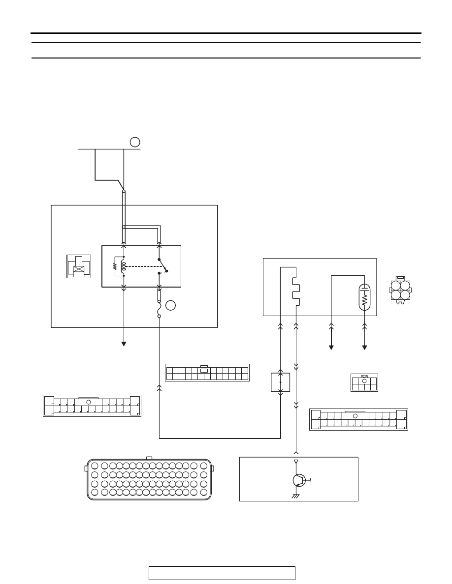
DTC P0037: Heated Oxygen Sensor (rear) Heater Circuit Low

AK704230

1

3

2

4

2

8

7

6

5

4

3

11

21

20

19

18

17

16

15

14

13

12

9

22

1

10

2

8

7

6

5

4

3

11

21

20

19

18

17

16

15

14

13

12

9

22

1

10

1 2

3 4

1

2

3 4 5 6 7 8 9 10 11 12 13 14 15 16

17 18 19 20 21 22 23 24 25 26 27 28 29 30 31 32

33 34 35 36 37 38 39 40 41 42 43 44 45 46 47 48

49 50 51 52 53 54 55 56 57 58 59 60 61 62 63 64

1

12 13 14 15 16 1718 19 20 2122 2324

2 3 4 5

6 7 8 9 10 11

1

2

3 4 5 6

WHITE

WHITE

HEATED OXYGEN SENSOR (REAR) HEATER CIRCUIT

36

FUSIBLE LINK

AB

D-35

4

1

20A

WHITE

A-34X

4

3

1

2

22

C-47

B-09

OFF

ON

C-43

1

4

2

3

RED-

GREEN

RED-

GREEN

11

10

2

C-45

A-13

35

J/C(4)

HEATED OXYGEN SENSOR
(REAR)

RELAY BOX
(ENGINE COMPARTMENT)

BR

O

W

N

BR

O

W

N

ENGINE
CONTROL
MODULE

TO ECM

TO ECM

TO ECM

MFI
RELAY

BR

O

W

N

MULTIPORT FUEL INJECTION (MFI) DIAGNOSIS

TSB Revision

MULTIPORT FUEL INJECTION (MFI)

13A-78

.

CIRCUIT OPERATION

• Power is supplied from the MFI relay (terminal 

No. 2) to the heated oxygen sensor (rear) heater.

• The ECM (terminal No. 35) controls continuity to 

the heated oxygen sensor (rear) heater by turn-
ing the power transistor in the ECM "ON" and 
"OFF".

.

TECHNICAL DESCRIPTION

• The ECM checks whether the heater current is 

within a specified range when the heater is ener-
gized.

• The ECM checks whether the heater voltage is 

within a specified range when the heater is not 
energized.

.

DESCRIPTIONS OF MONITOR METHODS

Heated oxygen sensor (rear) heater current or volt-

age is out of specified range.

.

MONITOR EXECUTION

Continuous

.

MONITOR EXECUTION CONDITIONS 
(Other monitor and Sensor)

Other Monitor (There is no temporary DTC stored 

in memory for the item monitored below)

• Not applicable

Sensor (The sensor below is determined to be 

normal)

• Not applicable

.

AK704229AB

Connector: A-13

A-13

AK704226

Connector: A-34X

MFI relay

A-34X

AB

AK704227

Connector: B-09

ECM

B-09 (GR)

AB

AK704231

Connectors: C-43, C-45 and C-47

C-47

C-45

C-43 (B)

AB

AK704232

Heated oxygen
sensor (rear)

Connector: D-35

D-35 (B)

AB

Rear heater
duct

MULTIPORT FUEL INJECTION (MFI) DIAGNOSIS

TSB Revision

MULTIPORT FUEL INJECTION (MFI)

13A-79

DTC SET CONDITIONS
Logic Flow Chart

.

Check Conditions

• More than 2 seconds have passed since the 

engine starting sequence was completed.

• While the heated oxygen sensor (rear) heater is 

on.

• Battery positive voltage is between 11 and 16.5 

volts.

Judgement Criterion

• The heated oxygen sensor (rear) heater current 

has continued to be lower than 0.17 ampere for 2 
seconds.

Check Conditions

• More than 2 seconds have passed since the 

engine starting sequence was completed.

• While the heated oxygen sensor (rear) heater is 

off.

• Battery positive voltage is between 11 and 16.5 

volts.

Judgement Criterion

• The heated oxygen sensor (rear) heater voltage 

has continued to be lower than 2.0 volts for 2 sec-
onds.

.

FAIL-SAFE AND BACKUP FUNCTION

• None

End

No

No

Malfunction

Good

Current < 0.17A

or

Current > 10.5A

Voltage < 2.0V

AK604306

Heater ON

No

No

Start

Yes

Yes

Yes

Yes

Yes

No

Continuous
failure for 2secs

Monitoring
conditions

MULTIPORT FUEL INJECTION (MFI) DIAGNOSIS

TSB Revision

MULTIPORT FUEL INJECTION (MFI)

13A-80

.

OBD-II DRIVE CYCLE PATTERN

Refer to Diagnostic Function 

− OBD-II Drive Cycle − 

Pattern 2 

P.13A-9

.

.

TROUBLESHOOTING HINTS (The most 
likely causes for this code to be set are:)

• Open or shorted heated oxygen sensor (rear) 

heater circuit, or harness damage.

• Heated oxygen sensor (rear) heater failed.

• Connector damage.

• ECM failed.

DIAGNOSIS

Required Special Tools:

• MB991658: Test Harness

• MB992110: Power Plant ECU Check Harness

STEP 1. Check harness connector D-35 at the heated 
oxygen sensor (rear) for damage.
Q: Is the harness connector in good condition?

YES : Go to Step 2.
NO :  Repair or replace it. Refer to GROUP 00E, Harness 

Connector Inspection 

P.00E-2

. Then go to Step 12.

STEP 2. Check the heated oxygen sensor (rear).
(1) Disconnect heated oxygen sensor (rear) connector D-35 

and connect test harness special tool, MB991658, to the 
connector on the heated oxygen sensor (rear) side.

(2) Measure the resistance between heated oxygen sensor 

connector terminal No. 1 and terminal No. 2.

Standard value: 4.5 

 8.0  [at 20° C (68° F)]

Q: Is the measured resistance between 4.5 and 8.0 

 [at 

20

° C (68° F)]?

YES : Go to Step 3.
NO :  Replace the heated oxygen sensor (rear). Then go to 

Step 12.

STEP 3. Measure the power supply voltage at heated 
oxygen sensor (rear) harness side connector D-35.
(1) Disconnect the connector D-35 and measure at the harness 

side.

(2) Turn the ignition switch to the "ON" position.
(3) Measure the voltage between terminal No. 1 and ground.

• Voltage should be battery positive voltage.

(4) Turn the ignition switch to the "LOCK" (OFF) position.
Q: Is battery positive voltage (approximately 12 volts) 

present?
YES : 
Go to Step 5.
NO :  Go to Step 4.

AK604492AB

MB991658

Heated oxygen
sensor component
side connector

AK604172

2 1
4 3

D-35 harness
connector:
component side 

AI


Content   ..  273  274  275  276   ..