Mitsubishi Evolution X. Manual - part 273


  Index      Mitsubishi     Mitsubishi Evolution X - service repair manual 2008 year


Search            


Content   ..  271  272  273  274   ..


Mitsubishi Evolution X. Manual - part 273


MULTIPORT FUEL INJECTION (MFI) DIAGNOSIS

TSB Revision

MULTIPORT FUEL INJECTION (MFI)

13A-69

TROUBLESHOOTING HINTS (The most 
likely causes for this code to be set are:)

• Open or shorted heated oxygen sensor (front) 

heater circuit, harness damage or connector 
damage.

• Heated oxygen sensor (front) heater failed.

• ECM failed. 

DIAGNOSIS

Required Special Tools:

• MB991658: Test Harness

• MB992110: Power Plant ECU Check Harness

STEP 1. Check harness connector C-34 at the heated 
oxygen sensor (front) for damage.
Q: Is the harness connector in good condition?

YES : Go to Step 2.
NO :  Repair or replace it. Refer to GROUP 00E, Harness 

Connector Inspection 

P.00E-2

. Then go to Step 12.

STEP 2. Check the heated oxygen sensor (front).
(1) Disconnect heated oxygen sensor (front) connector C-34 

and connect test harness special tool, MB991658, to the 
connector on the heated oxygen sensor (front) side.

(2) Measure the resistance between heated oxygen sensor 

connector terminal No. 1 and terminal No. 2.

Standard value: 4.5 

 8.0  [at 20° C (68° F)]

Q: Is the measured resistance between 4.5 and 8.0 

 [at 

20

° C (68° F)]?

YES : Go to Step 3.
NO :  Replace the heated oxygen sensor (front). Then go to 

Step 12.

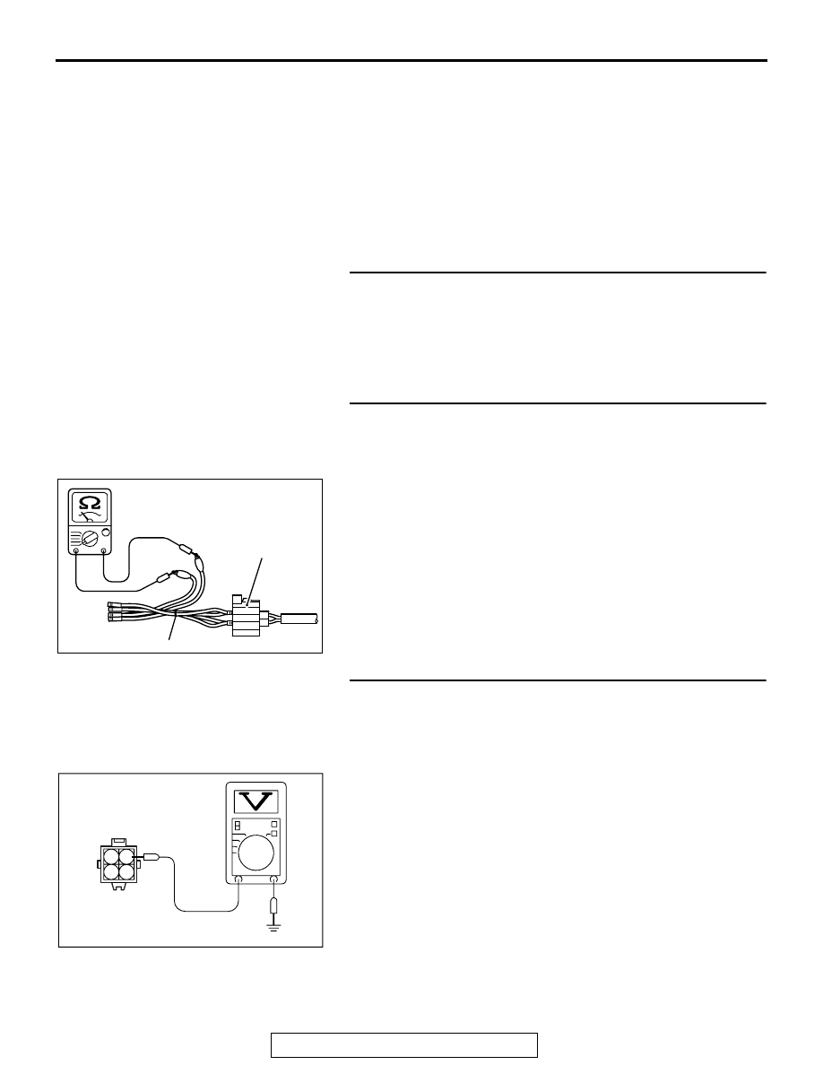
STEP 3. Measure the power supply voltage at heated 
oxygen sensor (front) harness side connector C-34.
(1) Disconnect the connector C-34 and measure at the harness 

side.

(2) Turn the ignition switch to the "ON" position.
(3) Measure the voltage between terminal No. 1 and ground.

• Voltage should be battery positive voltage.

(4) Turn the ignition switch to the "LOCK" (OFF) position.
Q: Is battery positive voltage (approximately 12 volts) 

present?
YES : 
Go to Step 5.
NO :  Go to Step 4.

AK604492AB

MB991658

Heated oxygen
sensor component
side connector

AK604172

2 1
4 3

C-34 harness
connector:
component side 

AH

MULTIPORT FUEL INJECTION (MFI) DIAGNOSIS

TSB Revision

MULTIPORT FUEL INJECTION (MFI)

13A-70

STEP 4. Check harness connector A-34X at the MFI relay 
for damage.
Q: Is the harness connector in good condition?

YES : Repair harness wire between MFI relay connector 

A-34X (terminal No. 2) and heated oxygen sensor 
(front) connector C-34 (terminal No. 1) because of 
open circuit or short circuit to ground. Then go to Step 
12.

NO :  Repair or replace it. Refer to GROUP 00E, Harness 

Connector Inspection 

P.00E-2

. Then go to Step 12.

STEP 5. Measure the power supply voltage at ECM 
connector B-09 by using power plant ECU check harness 
special tool MB992110.
(1) Disconnect all ECM connectors. Connect the power plant 

ECU check harness special tool MB992110 between the 
separated connectors.

(2) Turn the ignition switch to the "ON" position.

(3) Measure the voltage between terminal No. 34 and ground.

• Voltage should be battery positive voltage.

(4) Turn the ignition switch to the "LOCK" (OFF) position.
Q: Is battery positive voltage (approximately 12 volts) 

present?
YES : 
Go to Step 8.
NO :  Go to Step 6.

AK604040

ECM

AB

Body side harness 

MB992110

AK604173

16 15 14 13 12 11 10 9 8 7 6 5 4 3

2

1

32 31 30 29 28 27 26 25 24 23 22 21 20 19 18 17

48 47 46 45 44 43 42 41 40 39 38 37 36 35 34 33

64 63 62 61 60 59 58 57 56 55 54 53 52 51 50 49

AB

Power plant ECU
check harness connector

MULTIPORT FUEL INJECTION (MFI) DIAGNOSIS

TSB Revision

MULTIPORT FUEL INJECTION (MFI)

13A-71

STEP 6. Check harness connector B-09 at ECM for 
damage.
Q: Is the harness connector in good condition?

YES : Go to Step 7.
NO :  Repair or replace it. Refer to GROUP 00E, Harness 

Connector Inspection 

P.00E-2

. Then go to Step 12.

STEP 7. Check for open circuit and short circuit to ground 
between heated oxygen sensor (front) connector C-34 
(terminal No. 2) and ECM connector B-09 (terminal No. 34).
NOTE: Check harness after checking intermediate connector 
A-13. If intermediate connector is damaged, repair or replace it. 
Refer to GROUP 00E, Harness Connector Inspection 

P.00E-2

Then go to Step 12.
Q: Is the harness wire in good condition?

YES : Replace the ECM. When the ECM is replaced, 

register the ID code. Refer to GROUP 42B, ID Code 
Registration Necessity Judgment Table <Vehicles 
with KOS> 

P.42B-12

 or GROUP 42C, ID Codes 

Registration Judgment Table <Vehicles with WCM> 

P.42C-9

. Then go to Step 12.

NO :  Repair it. Then go to Step 12.

STEP 8. Check harness connector B-09 at ECM for 
damage.
Q: Is the harness connector in good condition?

YES : Go to Step 9.
NO :  Repair or replace it. Refer to GROUP 00E, Harness 

Connector Inspection 

P.00E-2

. Then go to Step 12.

STEP 9. Check for harness damage between MFI relay 
connector A-34X (terminal No. 2) and heated oxygen 
sensor (front) connector C-34 (terminal No. 1).
Q: Is the harness wire in good condition?

YES : Go to Step 10.
NO :  Repair it. Then go to Step 12.

STEP 10. Check for harness damage between heated 
oxygen sensor (front) connector C-34 (terminal No. 2) and 
ECM connector B-09 (terminal No. 34).
NOTE: Check harness after checking intermediate connector 
A-13. If intermediate connector is damaged, repair or replace it. 
Refer to GROUP 00E, Harness Connector Inspection 

P.00E-2

Then go to Step 12.
Q: Is the harness wire in good condition?

YES : Go to Step 11.
NO :  Repair it. Then go to Step 12.

MULTIPORT FUEL INJECTION (MFI) DIAGNOSIS

TSB Revision

MULTIPORT FUEL INJECTION (MFI)

13A-72

STEP 11. Check the trouble symptoms.
(1) Carry out a test drive with the drive cycle pattern. Refer to 

Diagnostic Function 

− OBD-II Drive Cycle − Pattern 2 

P.13A-9

.

(2) Check the diagnostic trouble code (DTC).
Q: Is DTC P0031 set?

YES : Replace the ECM. When the ECM is replaced, 

register the ID code. Refer to GROUP 42B, ID Code 
Registration Necessity Judgment Table <Vehicles 
with KOS> 

P.42B-12

 or GROUP 42C, ID Codes 

Registration Judgment Table <Vehicles with WCM> 

P.42C-9

. Then go to Step 12.

NO :  It can be assumed that this malfunction is intermittent. 

Refer to GROUP 00, How to Use 
Troubleshooting/Inspection Service Points 

− How to 

Cope with Intermittent Malfunctions 

P.00-15

STEP 12. Test the OBD-II drive cycle.
(1) Carry out a test drive with the drive cycle pattern. Refer to 

Diagnostic Function 

− OBD-II Drive Cycle − Pattern 2 

P.13A-9

.

(2) Check the diagnostic trouble code (DTC).
Q: Is DTC P0031 set?

YES : Retry the troubleshooting.
NO :  The inspection is complete.


Content   ..  271  272  273  274   ..