Mitsubishi Evolution X. Manual - part 194


  Index      Mitsubishi     Mitsubishi Evolution X - service repair manual 2008 year


Search            


Content   ..  192  193  194  195   ..


Mitsubishi Evolution X. Manual - part 194


EXHAUST MANIFOLD

TSB Revision

ENGINE OVERHAUL

11B-23

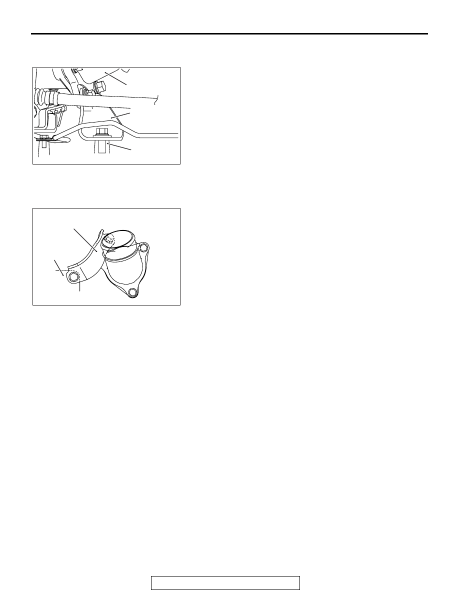
>>G<< EXHAUST FITTING BRACKET 
INSTALLATION

AK703142AC

Cylinder block

Exhaust fitting

Exhaust fitting
bracket

1. After temporarily tightening the exhaust fitting bracket with 

the installation bolts, check the exhaust manifold fastens 
securely to the cylinder block and the exhaust fitting.

2. Tighten the cylinder block side bolt to the specified 

tightening torque.

Specified torque: 51 

± 7 N⋅ m (38 ± 4 ft-lb)

3. Tighten the exhaust fitting bracket side bolt to the specified 

tightening torque.

Specified torque: 64 

± 5 N⋅ m (47 ± 3 ft-lb)

.

>>H<< TURBOCHARGER COMPRESSOR 
BRACKET INSTALLATION

AK703144AC

Turbocharger
compressor bracket

Cylinder block

1. After temporarily tightening the turbocharger compressor 

bracket with the installation bolts, check the exhaust 
manifold fastens securely to the cylinder block and the 
turbocharger.

2. Tighten the cylinder block side bolt to the specified 

tightening torque.

Specified torque: 51 

± 7 N⋅ m (38 ± 4 ft-lb)

3. Tighten the turbocharger side bolt to the specified tightening 

torque.

Specified torque: 51 

± 7 N⋅ m (38 ± 4 ft-lb)

WATER HOSE AND PIPE

TSB Revision

ENGINE OVERHAUL

11B-24

WATER HOSE AND PIPE

REMOVAL AND INSTALLATION

M1113032900249

AK702230

15

16

1

17

20

21

10 ± 2 N·m
89 ± 17 in-lb

18

19

8

9

6

30 ± 9 N·m
22 ± 6 ft-lb

7

5

10

11

12

13

AC

28 ± 8 N·m
21 ± 5 ft-lb

24 ± 3 N·m
18 ± 1 ft-lb

10 ± 2 N·m
89 ± 17 in-lb

2

4

14

3

22

23

10 ± 2 N·m
89 ± 17 in-lb

24 ± 3 N·m
18 ± 1 ft-lb

24 ± 3 N·m
18 ± 1 ft-lb

24 ± 3 N·m
18 ± 1 ft-lb

24 ± 3 N·m
18 ± 1 ft-lb

Removal steps 

1. Water hose
2. Water hose
3. Water hose
4. Water hose

>>E<<

5. Engine coolant temperature sensor
6. Water outlet fitting

>>D<<

7. Water outlet fitting gasket
8. Water inlet fitting

>>C<<

9. Thermostat

>>B<<

10. Thermostat housing
11. Thermostat housing gasket

>>B<<

12. Water pipe assembly

>>B<<

13. Water pipe gasket
14. O-ring
15. Water pump assembly
16. Water pump gasket
17. Engine hanger
18. Intake camshaft position sensor
19. O-ring
20. Exhaust camshaft position sensor
21. O-ring

>>A<<

22. Crankshaft position sensor
23. O-ring

Removal steps (Continued)

WATER HOSE AND PIPE

TSB Revision

ENGINE OVERHAUL

11B-25

INSTALLATION SERVICE POINTS

.

>>A<< CRANKSHAFT POSITION SENSOR 
INSTALLATION

CAUTION

• Do not apply a force such as torsion or twist to the 

O-ring during assembly of the sensor.

• Assemble the sensor, taking care not to give a shock to 

it.

• Do not use a sensor that has been dropped.

Tighten the crankshaft position sensor to the specified torque.

Specified torque: 10 

± 2 N⋅ m (89 ± 17 in-lb)

.

>>B<< THERMOSTAT HOUSING / WATER PIPE 
ASSEMBLY / WATER PIPE GASKET 
INSTALLATION

1. Assemble the thermostat housing and water pipe
2. Install the thermostat housing gasket.

AK703291AC

Tab

3. Install a new water pipe gasket so that the tab is positioned 

as shown in the illustration.

4. Temporarily tighten them to the cylinder head and water 

pump. Then tighten them to the specified torque.

Specified torque: 24 

± 3 N⋅ m (18 ± 1 ft-lb)

.

>>C<< THERMOSTAT INSTALLATION 

AK703293AC

Jiggle valve

Install the thermostat with the jiggle valve facing almost straight 
upwards.

.

WATER HOSE AND PIPE

TSB Revision

ENGINE OVERHAUL

11B-26

>>D<< WATER OUTLET FITTING GASKET 
INSTALLATION

AK703292AC

Tab

Tab

Install a new gasket so that the tab is positioned as shown in 
the illustration.

.

>>E<< ENGINE COOLANT TEMPERATURE 
SENSOR INSTALLATION

CAUTION

Be careful not to give a shock, twist and the like to the 
resin mold with a tool during installation.

AK502544 AD

1. Apply an appropriate and minimum amount of sealant 

(LOCTITE 262, Three bond 1324N or equivalent) to the 
engine coolant temperature sensor, taking care not to allow 
sealant to squeeze out.

2. Tighten the engine coolant temperature sensor to the 

cylinder block to the specified torque.

Specified torque: 30 

± 9 N⋅ m (22 ± 6 ft-lb)


Content   ..  192  193  194  195   ..