Mitsubishi Evolution X. Manual - part 183


  Index      Mitsubishi     Mitsubishi Evolution X - service repair manual 2008 year


Search            


Content   ..  181  182  183  184   ..


Mitsubishi Evolution X. Manual - part 183


CYLINDER HEAD GASKET

TSB Revision

ENGINE MECHANICAL

11A-63

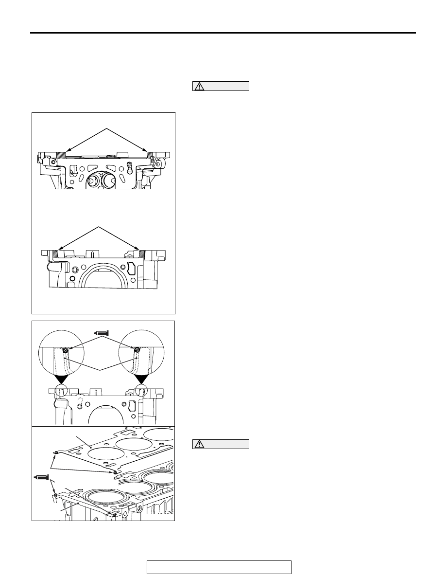
INSTALLATION SERVICE POINTS

.

>>A<< CYLINDER HEAD GASKET/CYLINDER 
HEAD ASSEMBLY INSTALLATION

CAUTION

Do not allow any foreign materials get into the coolant pas-
sages, oil passages and cylinder.
1. Remove the sealant and grease on the top surface of 

cylinder block and on the bottom surface of the cylinder 
head. Then, use the quick-drying degreasing agent (white 
gasoline) to degrease the sealant application surface.

2. Apply the sealant to the top surface of cylinder block as 

shown in the figure.

Specified sealant: Three bond 1217G

3. Within three minutes after the sealant application, install the 

cylinder head gasket to the cylinder block.
NOTE: When the cylinder gasket is installed to the cylinder 
block, check that the sealant is securely applied to the bead 
line of the cylinder head gasket.

4. Apply the sealant to the top surface of cylinder head gasket 

as shown in the figure.

Specified sealant: Three bond 1217G

CAUTION

Within two hours after the cylinder head assembly installa-
tion, do not apply oil or water to the sealant application 
area or start the engine.
5. Within three minutes after the sealant application, install the 

cylinder head assembly.

.

AC607682AB

Degrease

Degrease

Bottom view of cylinder head

Top view of cylinder block

AC511063

AD

φ 2 mm or φ 3 mm (φ 0.08 in or φ 0.12 in)

Cylinder head
gasket

Cylinder head 
gasket

Cylinder 
block

φ 2 mm or φ 3 mm
(

φ 0.08 in or φ 0.12 in)

CYLINDER HEAD GASKET

TSB Revision

ENGINE MECHANICAL

11A-64

>>B<< CYLINDER HEAD BOLT AND WASHER 
ASSEMBLY/CYLINDER HEAD BOLT 
WASHER/CYLINDER HEAD BOLT INSTALLATION

1. Replace the cylinder head bolt and washer with new ones.
2. For two bolts of the timing chain side, the washer can be 

removed from the bolt. Install the washer, with its sag facing 
upward, to the bolts.

3. Apply a small amount of engine oil to the thread of the bolts 

and to the washers.

4. Tighten the bolts by the following procedure (plastic region 

angular tightening method).

(1) Tighten the bolts to 35 

± 2 N⋅ m (26 ± 1 ft-lb) in the order 

of number shown in the figure.

CAUTION

• When the tightening angle is smaller than the specified 

tightening angle, the appropriate tightening capacity 
cannot be secured.

• When the tightening angle is larger than the specified 

tightening angle, remove the bolt to start from the 
beginning again according to the procedure.

(2) Apply paint marks to the head of cylinder head bolt and 

the cylinder head.

(3) Tighten the cylinder head to 90

°  in the tightening order. 

Additionally tighten to 90

° , and check that the paint mark 

on the cylinder head bolt is aligned with the paint mark on 
the cylinder head.

AC506767AE

1

2

3

4

5

6

7

8

9

10

Engine front

AC708680AC

90˚

90˚

Paint mark

Paint mark

Paint marks

Paint marks

CYLINDER HEAD GASKET

TSB Revision

ENGINE MECHANICAL

11A-65

5. Install special tool MB991928 or MB991895 which was 

installed for supporting the engine and transaxle assembly 
when the valve timing chain was removed (Refer to 

P.11A-69

).

6. Remove the garage jack which supports the engine and 

transaxle assembly.

7. Remove the engine oil pan installed temporarily.

.

AC705461

MB991454

AC

MB991928

AC705462

MB991454

AC

MB991895

CYLINDER HEAD GASKET

TSB Revision

ENGINE MECHANICAL

11A-66

>>C<< CAMSHAFT BEARING/CAMSHAFT AND 
CAMSHAFT SPROCKET ASSEMBLY 
INSTALLATION

CAUTION

• Be careful not to drop the camshaft bearing.
• When installing the camshaft and camshaft sprocket 

assembly (exhaust side), be careful not to let the cam-
shaft bearing which is installed to the front cam bearing 
deviate from its position.

When replacing the camshaft bearing, according to the identifi-
cation mark of front camshaft bearing cap in the table below, 
select a camshaft bearing with the corresponding size. Note 
that the identification mark of camshaft bearing is stamped on 
the place shown in the figure.

.

Front camshaft bearing cap

Camshaft bearing 
identification mark

Identification 
mark

Journal diameter 
mm (in)

1

40.000 - 40.008 
(1.5748 - 1.5751)

1

2

40.008 - 40.016 
(1.5751 - 1.5754)

2

3

40.016 - 40.024 
(1.5754 - 1.5757)

3

AC611697

AD

Front camshaft 
bearing cap

Identification
mark

AC708893

Notch

Identification mark

Oil hole

AD


Content   ..  181  182  183  184   ..