Mitsubishi Evolution X. Manual - part 182
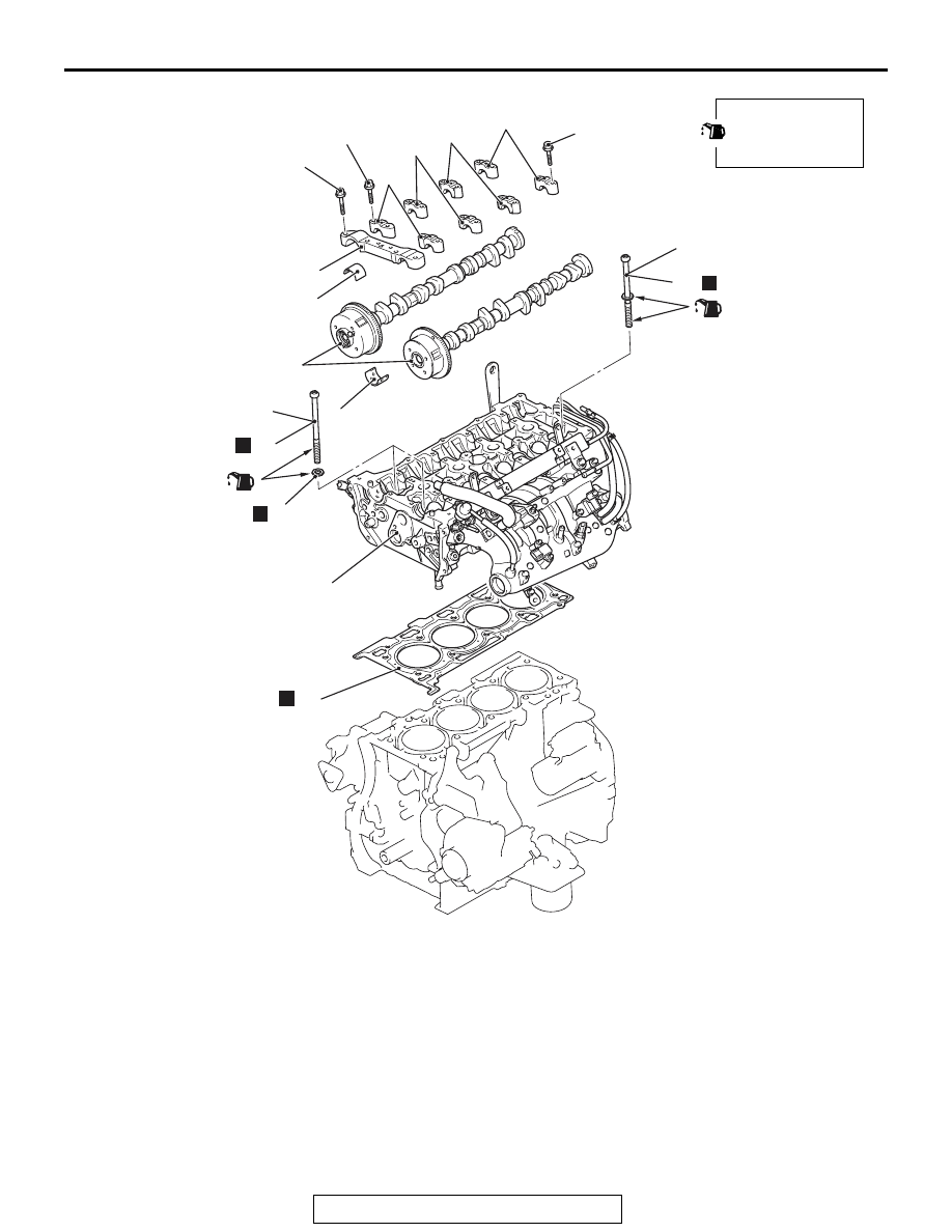
CYLINDER HEAD GASKET
TSB Revision
ENGINE MECHANICAL
11A-59
AC706764AC
30
26
29
24
N
23
20
18
21
22
N
28
N
19
25
27
N
12 ± 1 N·m
107 ± 8 in-lb
17 ± 3 N·m
13 ± 2 ft-lb
Apply engine oil to all
moving parts before
installation.
(Engine oil)
(Engine oil)
12 ± 1 N·m
107 ± 8 in-lb
<Cold engine>
35 ± 2 N·m
26 ± 1 ft-lb
30 ± 2 N·m
23 ± 1ft-lb
to
to +90˚ to +90˚
<Cold engine>
35 ± 2 N·m
26 ± 1 ft-lb to +90˚ to +90˚
Removal steps
•
Valve timing chain (Refer to
)
<<
B
>>
>>
E
18. Front camshaft bearing cap
assembly
>>
C
<<
19. Camshaft bearing
<<
C
>>
>>
D
<<
20. Oil feeding camshaft bearing cap
<<
C
>>
>>
D
<<
21. Camshaft bearing cap
<<
C
>>
>>
D
<<
22. Camshaft bearing cap
<<
C
>>
>>
D
<<
23. Thrust camshaft bearing cap
>>
C
24. Camshaft and camshaft sprocket
assembly
>>
C
25. Camshaft bearing
<<
D
>>
>>
B
26. Cylinder head bolt
<<
D
>>
>>
B
27. Cylinder head bolt washer
<<
D
>>
>>
B
28. Cylinder head bolt and washer
assembly
>>
A
29. Cylinder head assembly
>>
A
30. Cylinder head gasket
Removal steps (Continued)