Mitsubishi Evolution X. Manual - part 1291


  Index      Mitsubishi     Mitsubishi Evolution X - service repair manual 2008 year


Search            


Content   ..  1289  1290  1291  1292   ..


Mitsubishi Evolution X. Manual - part 1291


ON-VEHICLE SERVICE

TSB Revision

HEATER, AIR CONDITIONING AND VENTILATION

55-115

PERFORMANCE TEST 

M1552001400957

The vehicles to be tested should be parked out of direct sun-
light.
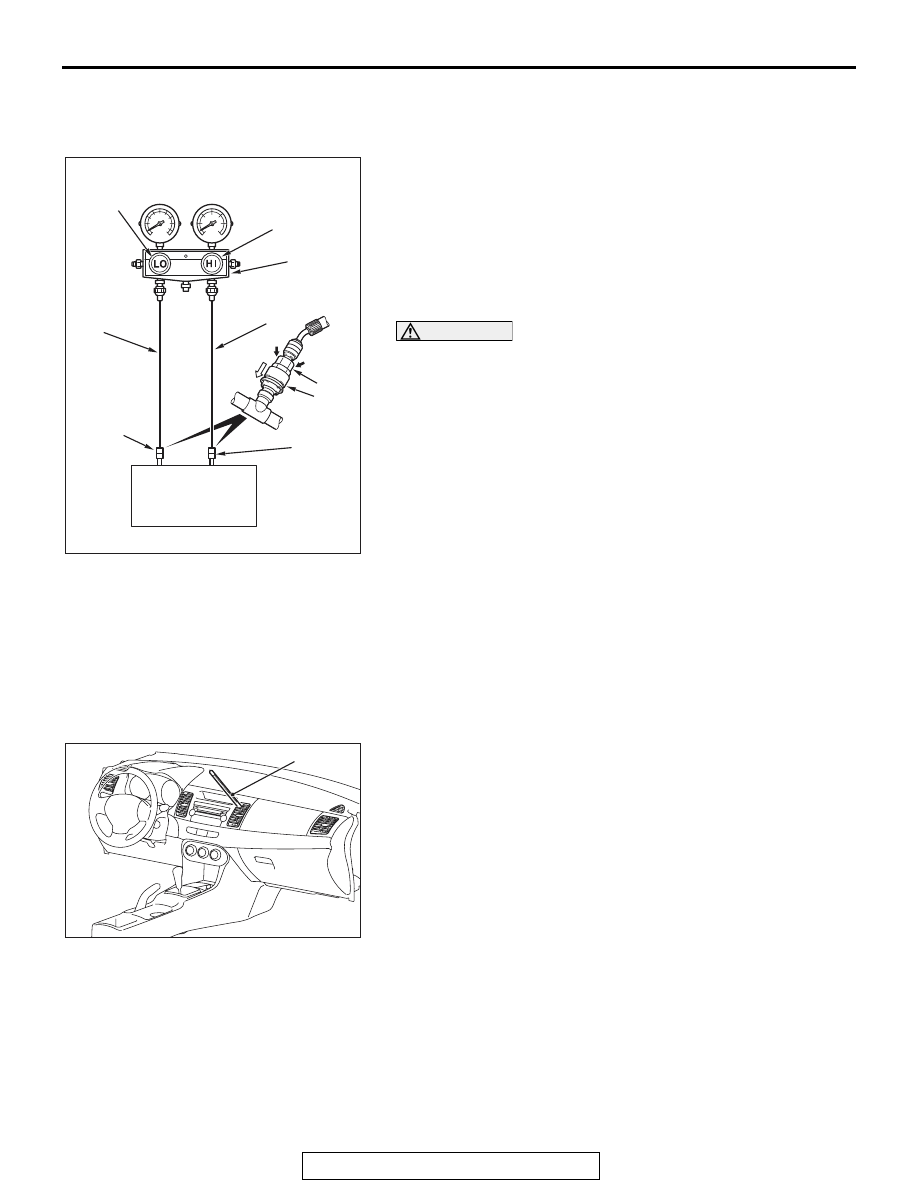
1. Close the high and low-pressure valve of the gauge 

manifold.

2. Connect the charging hose (blue) to the low-pressure valve 

and connect the charging hose (red) to the high-pressure 
valve of the gauge manifold.

3. Install the quick joint (for low-pressure) to the charging hose 

(blue), and connect the quick joint (for high-pressure) to the 
charging hose (red).

CAUTION

• To connect the quick joint, press section A firmly 

against the service valve until a click is heard.

• When connecting, run your hand along the hose while 

pressing to ensure that there are no bends in the hose.

4. Connect the quick joint (for low-pressure) to the 

low-pressure service valve and connect the quick joint (for 
high-pressure) to the high-pressure service valve.
NOTE: The high-pressure service valve is on the A/C pipe 
and the low-pressure service valve is on the suction hose.

5. Start the engine.
6. Set the A/C controls as follows:

• A/C switch: A/C − ON position

• Mode selection: FACE position

• Temperature control: MAXIMUM COOLING position

• Air selection: RECIRCULATION position

• Blower switch: Maximum air volume 

7. Set the engine speed to the idle speed.
8. Engine should be warmed up with hood, doors and windows 

opened.

9. Insert a thermometer in the center air outlet and operate the 

engine for 20 minutes.
NOTE: If the A/C clutch cycles, take the reading before the 
clutch disengages.

10.Note the discharge air temperature.

AC609415

Low-pressure
valve

High-pressure
valve

Gauge manifold

Charging
hose (Red)

A

Sleeve

Charging
hose (Blue)

Adaptor
valve
(For
low-pres-
sure)

Adaptor
valve
(For high-
pressure)

Low-
pressure
service 
valve

High-
pressure
service
valve

AC

AC609414AB

Thermometer

ON-VEHICLE SERVICE

TSB Revision

HEATER, AIR CONDITIONING AND VENTILATION

55-116

PERFORMANCE TEMPERATURE CHART

REFRIGERANT LEAK REPAIR PROCEDURE

M1552001500448

LOST CHARGE

If the system has lost all charge due to a leak:
1. Evacuate the system. (Refer to 

P.55-114

).

2. Charge the system with approximately 0.453 kg (1 

pound) of refrigerant.

3. Check for leaks.
4. Discharge the system.
5. Repair leaks.

CAUTION

Replacement filter-drier units must be sealed 
while in storage. The drier used in these units will 
saturate water quickly upon exposure to the 
atmosphere. When installing a drier, have all 
tools and supplies ready for quick assembly to 
avoid keeping the system open any longer than 
necessary.
6. Replace receiver drier.
7. Evacuate and charge system.

LOW CHARGE

If the system has not lost all of its refrigerant charge; 
locate and repair all leaks. If it is necessary to 
increase the system pressure to find the leak 
(because of an especially low charge) add refriger-
ant. If it is possible to repair the leak without dis-
charging the refrigerant system, use the procedure 
for correcting low refrigerant level.

HANDLING TUBING AND FITTINGS

Kinks in the refrigerant tubing or sharp bends in the 
refrigerant hose lines will greatly reduce the capacity 
of the entire system. High pressures are produced in 
the system when it is operating. Extreme care must 
be exercised to make sure that all connections are 
pressure tight. Dirt and moisture can enter the sys-
tem when it is opened for repair or replacement of 
lines or components. The following precautions must 
be observed. The system must be completely dis-
charged before opening any fitting of connection in 
the refrigeration system. Open fittings with caution 
even after the system has been discharged. If any 
pressure is noticed as a fitting is loosened, allow 
trapped pressure to bleed off very slowly.
Never attempt to rebend formed lines to fit. Use the 
correct line for the installation you are servicing. A 
good rule for the flexible hose lines is keep the radius 
of all bends at least 10 times the diameter of the 
hose.
Sharper bends will reduce the flow of refrigerant. The 
flexible hose lines should be routed so that they are 
at least 80 mm (3.1 inches) from the exhaust mani-
fold. It is good practice to inspect all flexible hose 
lines at least once a year to make sure they are in 
good condition and properly routed.
On standard plumbing fittings with O-rings, these 
O-rings are not reusable.

Garage 
ambient air 
temperature 
° C (° F)

20 (68)

25 (77)

30 (86)

35 (95)

40 (104)

45 (113)

50 (122)

Discharge air 
temperature 
° C (° F)

4.7 (40) 

− 

17 (63)

10 (50) 

− 23 

(73)

15 (59) 

− 28 

(82)

20 (68) 

− 33 

(91)

26 (79) 

− 38 

(100)

31 (88) 

− 44 

(111)

36 (97) 

− 49 

(120)

Compressor 
high pressure 
kPa (psi)

934 (136) 

− 

1700 (247)

1068 (155) 
− 1850 

(268)

1201 (174) 
− 2000 

(290)

1335 (193) 
− 2150 

(312)

1468 (213) 
− 2300 

(334)

1602 (232) 
− 2450 

(355)

1735 (252) 
− 2600 

(377)

Compressor 
low pressure 
kPa (psi)

170 (24.7) 

− 

359 (52.1)

215 (31.2) 

− 

406 (58.9)

260 (37.7) 

− 

452 (65.6)

305 (44.2) 

− 

499 (72.4)

350 (50.8) 

− 

545 (79.1)

395 (57.3) 

− 

592 (85.9)

440 (63.8) 

− 

638 (92.6)

ON-VEHICLE SERVICE

TSB Revision

HEATER, AIR CONDITIONING AND VENTILATION

55-117

COMPRESSOR NOISE CHECK

M1552008700487

You must first know the conditions when the noise 
occurs. These conditions are: weather, vehicle 
speed, in gear or neutral, engine temperature or any 
other special conditions.
Noises that develop during A/C operation can often 
be misleading. For example: what sounds like a 
failed front bearing or connecting rod, may be 
caused by loose bolts, nuts, mounting brackets, or a 
loose clutch assembly. Verify accessory drive belt 
tension (power steering or generator).
Improper accessory drive belt tension can cause a 
misleading noise when the compressor is engaged 
and little or no noise when the compressor is disen-
gaged.
Drive belts are speed-sensitive. That is, at different 
engine speeds, and depending upon belt tension, 
belts can develop unusual noises that are often mis-
taken for mechanical problems within the compres-
sor.

ADJUSTMENT

1. Select a quiet area for testing. Duplicate 

conditions as much as possible. Switch the 
compressor on and off several times to clearly 
identify compressor noise. To duplicate high 
ambient conditions (high head pressure), restrict 
air flow through the condenser. Install a manifold 
gauge set to make sure discharge pressure 
doesn't exceed 2,070 kPa (300.2 psi).

2. Tighten all compressor mounting bolts, clutch 

mounting bolt, and compressor drive belt. Check 
to assure clutch coil is tight (no rotation or 
wobble).

3. Check refrigerant hoses for rubbing or 

interference that can cause unusual noises.

4. Check refrigerant charge (Refer to 

P.55-114

).

5. Recheck compressor noise as in Step 1.
6. If noise still exists, loosen compressor mounting 

bolts and retighten. Repeat Step 1.

7. If noise continues, replace compressor and repeat 

from Step 1.

POWER RELAY CHECK

M1552008800967

A/C COMPRESSOR CLUTCH RELAY CONTINUITY 
CHECK

Battery voltage

Tester connection Specified 

condition

Not applied

− 4

Open circuit

• Connect 

terminal 2 to the 
positive battery 
terminal

• Connect 

terminal 1 to the 
negative battery 
terminal

− 4

Less than 2 ohms

AC605626

AC609971

AB

4

1

2

3

3

1

4

2

A/C compressor clutch relay

ON-VEHICLE SERVICE

TSB Revision

HEATER, AIR CONDITIONING AND VENTILATION

55-118

BLOWER RELAY CONTINUITY CHECK

IDLE-UP OPERATION CHECK

M1552001601169

Before inspection and adjustment, set vehicle in the following 

condition:

• Engine coolant temperature: 80 − 90 ° C (176.0 − 194.0 ° F)

• Lights, electric cooling fan and accessories: OFF

• Transmission: Neutral ("N" or "P" position)

• Steering wheel: Straightforward

1. Check whether or not the idle speed is the standard value. 

Refer to GROUP 11A, On-vehicle Service 

− Idle Speed 

Check 

P.11A-12

.

Standard value: 700 

± 50 r/min

2. Turn on the air conditioning switch and the blower speed 

selection dial. Engine idling speed should be within the 
standard value:

Standard value: 800 

± 50 r/min

NOTE: It is not necessary to make an adjustment, because 
the idling speed is automatically adjusted by the ISC sys-
tem. If, however, a deviation from the standard value occurs 
for some reason, check the ISC system (Refer to GROUP 
11A, On-vehicle Service 

 Idle Speed Check 

P.11A-12

)

Battery voltage

Tester connection Specified 

condition

Not applied

− 4

Open circuit

• Connect 

terminal 1 to the 
positive battery 
terminal

• Connect 

terminal 2 to the 
negative battery 
terminal

− 4

Less than 2 ohms

AC605627

AC609984

AB

Blower relay

4

1

2

3

4

1

3

2


Content   ..  1289  1290  1291  1292   ..