Content .. 1287 1288 1289 1290 ..
Mitsubishi Evolution X. Manual - part 1289
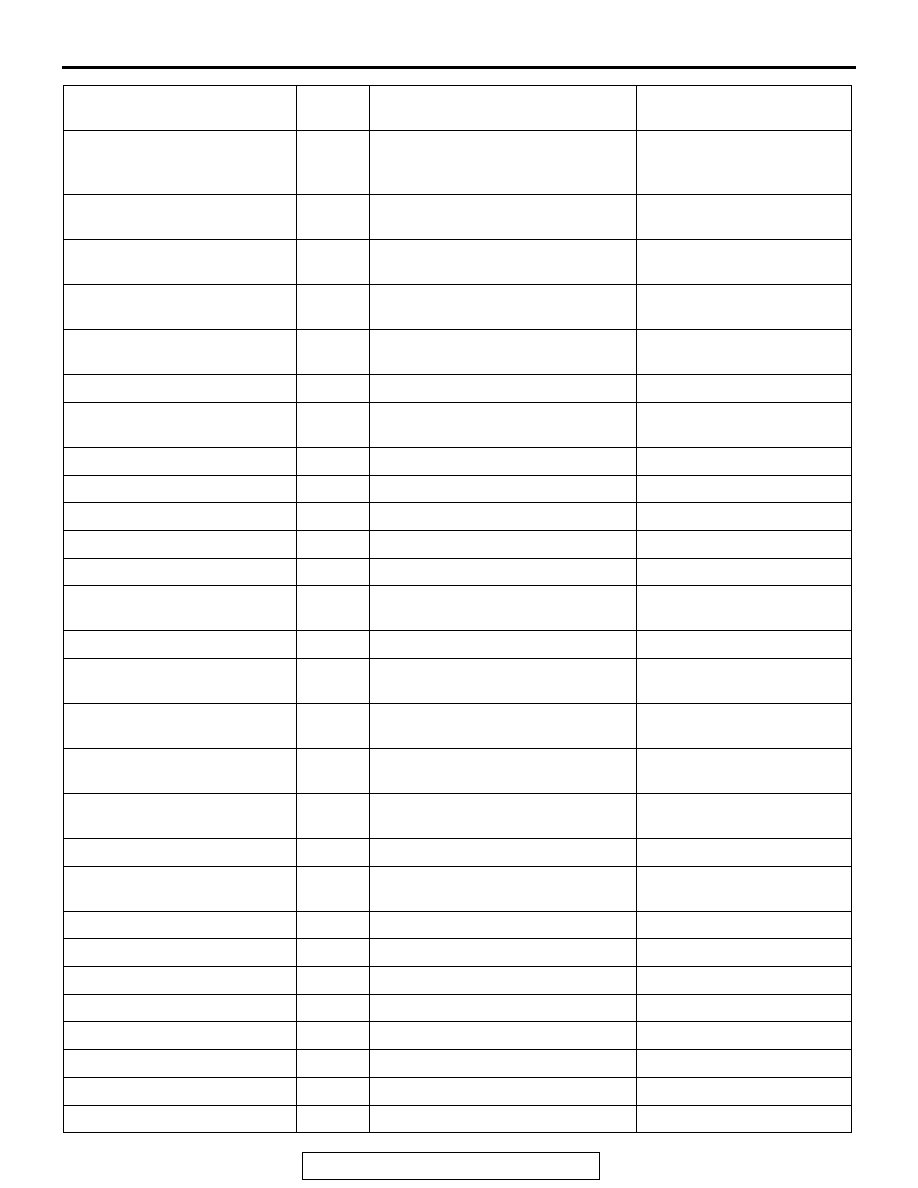
AUTO A/C DIAGNOSIS
TSB Revision
HEATER, AIR CONDITIONING AND VENTILATION
55-107
In/out air c/o SW light
90
−
Displays the status of the
inside air/outside air
changeover switch indicator.
A/C Compressor drive flag
91
−
ON when the compressor is
activated.
Wiper operation flag
92
−
ON when the wiper is
operated.
Ignition position information
93
−
Ignition switch position
status
Power source voltage
94
−
Displays power supply
voltage.
IOD fuse equipment flag
95
−
IOD fuse status
A/T lock up open request
96
−
Displays A/T lock open
request signal.
System operation time
100
−
−
Compressor use times
101
−
−
Rear defogger use times
102
−
−
In/out air c/o poten drive time
103
−
−
Air outlet c/o poten drive time
104
−
−
Air mix potentiometer drive
time
105
−
−
Hot state time (Interior TEMP.) 106
−
−
Cold state time (Interior
TEMP.)
107
−
−
Hot state time (Ambient
TEMP.)
108
−
−
Cold state time (Ambient
TEMP.)
109
−
−
Maximum ambient
temperature
110
−
−
Minimum ambient temperature 111
−
−
Maximum Engine coolant
TEMP.
112
−
−
Engine high speed time
113
−
−
Maximum Engine speed
114
−
−
High pressure drive time
115
−
−
High pressure cut times
116
−
−
Maximum pressure (kPa)
117
−
−
A/C use rate
118
−
−
Compressor operation rate
119
−
−
Eco operation rate
120
−
−
Scan tool display
Item
No.
Inspection status
The display content under
normal condition