Mitsubishi Evolution X. Manual - part 72
HEATER CONTROL
TSB Revision
HEATER, AIR CONDITIONING AND VENTILATION
55-8
HEATER CONTROL
M2551000900584
HEATER CONTROLLER
.
The features of the heater controller described below
have been designed for better appearance, easier
operation, and enhanced visibility.
• Each dial for the air outlet switching, fan volume
control, and temperature adjustment has been
enlarged to enhance operability.
• Ring lights have been adopted to inside the dials
to enhance appearance during nighttime.
• AUTO and OFF positions of the fan volume con-
trol dial have been exchanged with one another.
This change prevents the dial to pass the AUTO
position when the fan volume control is turned
OFF, and eliminates the necessity of manual
reselection when switching the inside/outside air
selection manually, thus enhancing the operabil-
ity.
• When the air outlet switching dial and fan volume
control dial are turned to the AUTO position, the
A/C switch has been made to automatically turn
ON to enhance convenience. (Using the custom-
ize function, this function can be cancelled. Refer
to
.)
AC608069
AC608068
AC708613
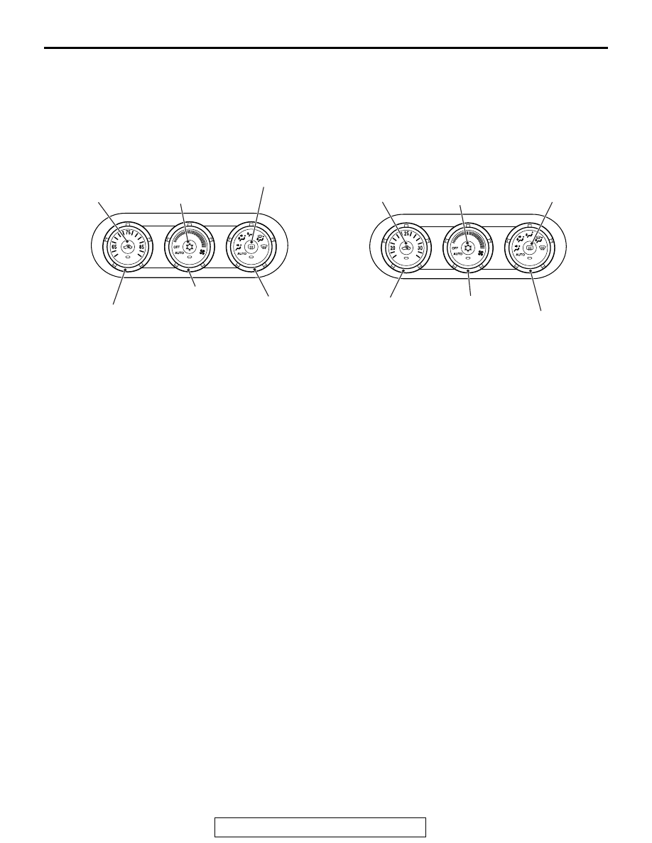
<Vehicles for USA>
Outside/Inside air
selection switch
Temperature adjustment knob
A/C switch
Blower knob
Mode selection knob
Rear window defogger switch
<Vehicles for CANADA>
Outside/Inside air
selection switch
Temperature
adjustment knob
Blower knob
A/C switch
Mode selection knob
Rear window
defogger switch
AB