Mitsubishi Evolution X. Manual - part 71
GENERAL DESCRIPTION
TSB Revision
HEATER, AIR CONDITIONING AND VENTILATION
55-4
AC708612
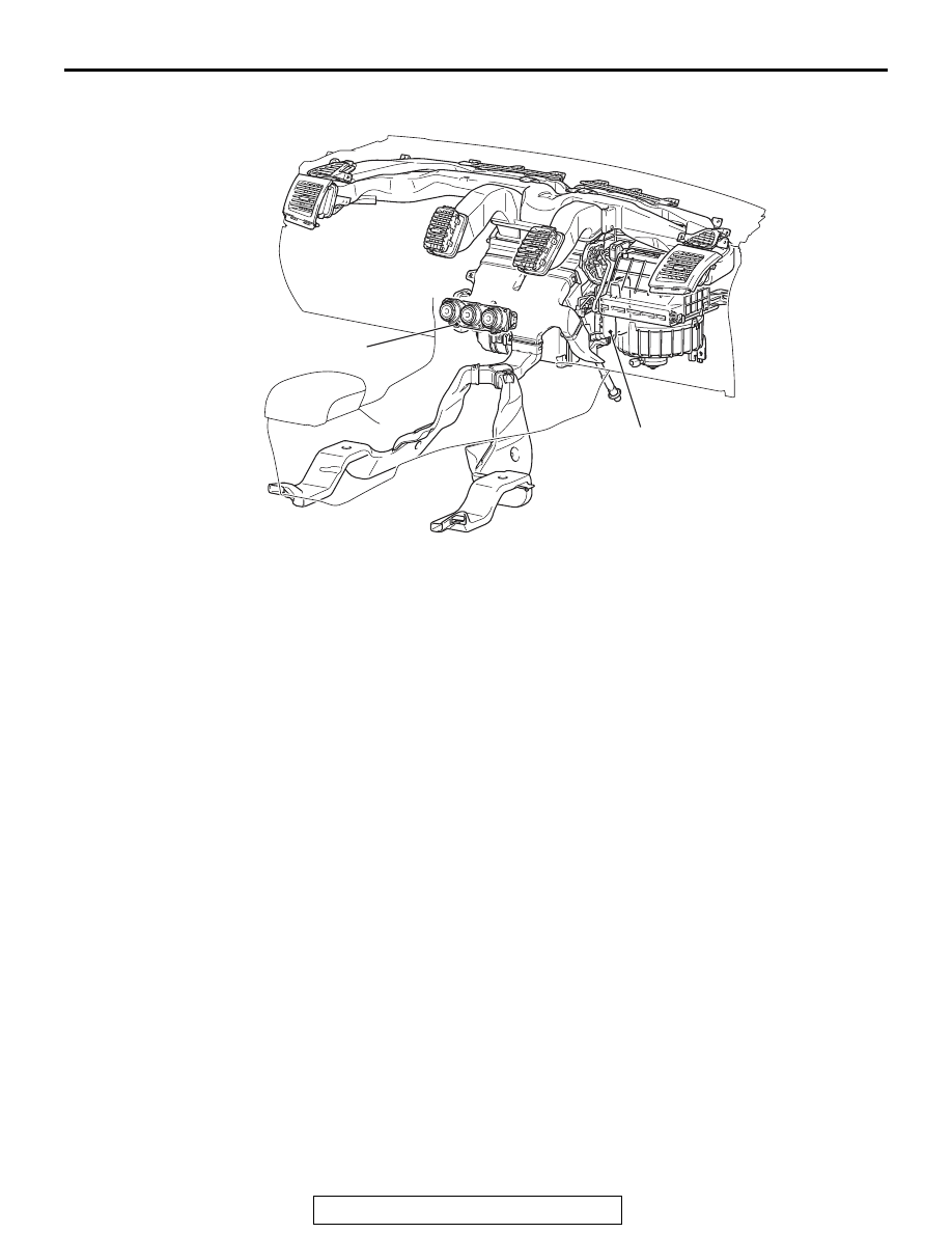
A/C-ECU
A/C control panel
|
|
|
GENERAL DESCRIPTION TSB Revision HEATER, AIR CONDITIONING AND VENTILATION 55-4 AC708612 A/C-ECU A/C control panel |