Mitsubishi Evolution X. Manual - part 8


  Index      Mitsubishi     Mitsubishi Evolution X - service repair manual 2008 year


Search            


Content   ..  6  7  8  9   ..


Mitsubishi Evolution X. Manual - part 8


BODY REPAIR

TSB Revision

BASE OF BODY REPAIR

9-29

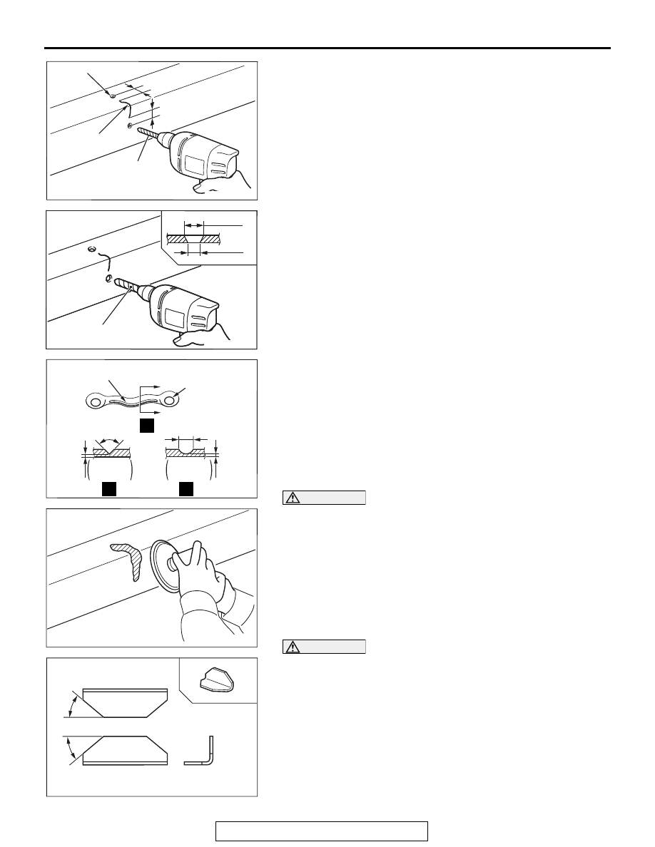
1. Remove the components near the crack.
2. Make 

φ 6 − 8 mm (0.24 − 0.31 inch) holes (to prevent further 

cracking), by using a drill, at points 7 

− 8 mm (0.28 − 0.31 

inch) from the crack ends.

3. Use a 

φ 10 − 12 mm (0.39 − 0.47 inch) drill to bevel the hole 

openings.

4. Use a chisel or gouging tool to open up the crack and holes, 

and then fill the crack and holes by MIG welding.

CAUTION

• Gas welding should be avoided because it causes ther-

mal distortion of the frame.

• When using a grinder for finishing, be careful not to 

grind the frame excessively.

5. Using a grinder for finishing after welding.

CAUTION

• The reinforcement plate should completely cover the 

cracked part.

• The reinforcement plate should be the same thickness 

and material as the frame.

6. To avoid a concentration of stress, prepare a reinforcement 

plate that has been cut to 30 

− 45 degree angle at both 

ends.

AB301469

Crack-stop hole

Crack

A

A

Ø6 – 8 mm
(0.24 – 0.31 in)

A : 7 – 8 mm (0.28 – 0.31 in)

AD

AB301470AB

Ø10 – 12 mm
(0.39 – 0.47 in)

Ø10 

 12 mm

Ø6 

 8 mm

AB301470 AC

(0.24 

 0.31 in)

(0.39 

 0.47 in)

AB301471AD

Crack

Crack-stop
hole

Approx.
8 mm
(0.31 in)

 Approx.
   1 mm 
   (0.04 in)

Approx.
1 mm 
(0.04 in)

Approx.

90˚

If a chisel 
is used

If a gouge 
is used

A

A

A

AB200131AB

AB301461

A

A

A : 30 – 45˚

AB

BODY REPAIR

TSB Revision

BASE OF BODY REPAIR

9-30

CAUTION

Be sure that the edges of the reinforcement plate are not 
near any place where a concentration of stress of the 
crossmember or spring hanger installation part, etc. could 
easily occur.
7. Attach the reinforcement plate to the repaired crack area by 

MIG welding. In order to avoid a concentration of stress at 
the time, weld the reinforcement plate at points about 10 mm 
(0.39 inch) from its edges.

NOTE: If the crack is at the upper side of the frame, attach 
the reinforcement plate facing downward, as shown in (1).
If the crack is at the lower side, attach the reinforcement 
plate to face upward, as shown in (2).

8. Finally, apply a coating of chassis black to the repaired area 

and to any places where the coating has flaked off.

AB200133

10 mm (0.39 in)

Welded point

AD

AB200133

AB200134

AB200134AB

(2)

(1)

BODY REPAIR

TSB Revision

BASE OF BODY REPAIR

9-31

NOTES REGARDING REPAIR WORK

M4090015000039

SAFETY MEASURES

.

PROTECTIVE GEAR

During body repair work, a work suit, a work cap, and safety 
shoes should be worn at all times. Depending on the work 
being done, safety glasses, gloves, ear protectors, a dustproof 
mask, etc., should also be worn as needed.

1. Safety glasses
2. Work cap
3. Ear protectors
4. Head protector
5. Work suit
6. Dustproof mask
7. Work apron
8. Welding gloves
9. Foot and ankle protectors

10. Safety shoes
11. Work gloves

.

SUPPLEMENTAL RESTRAINT SYSTEM 
(SRS)

1. Items to review when servicing SRS

(1) Be sure to read Service Manual GROUP 52B, 

Supplemental Restraint System (SRS). For 
safe operation, please follow the directions 
and heed all warnings.

(2) Wait at least 60 seconds after disconnecting 

the battery cable before doing any further 
work. The SRS system is designed to retain 
enough voltage to deploy the air bag even 
after the battery has been disconnected. 
Serious injury may result from unintended air 
bag deployment if work is done on the SRS 
system immediately after the battery cable is 
disconnected.

(3) Warning labels must be heeded when 

servicing or handling SRS components. 

(4) Always use the designated special tools and 

test equipment.

(5) Store components removed from the SRS in a 

clean and dry place. The air bag module 
should be stored on a flat surface and placed 
so that the pad surface is facing upward.

(6) Never attempt to disassemble or repair the 

SRS components (SRS-ECU, air bag module 
and clock spring). If there is a defect, replace 
the defective part.

(7) Whenever you finish servicing the SRS, check 

the SRS warning light operation to make sure 
that the system functions properly.

(8) Be sure to deploy the air bag before disposing 

of the air bag module or disposing of a vehicle 
equipped with an air bag. 

2. Observe the following when carrying out 

operations on places where SRS components are 
installed, including operations not directly related 
to the SRS air bag.
(1) When removing or installing parts, do not allow 

any impact or shock to occur to the SRS 
components.

(2) If heat damage may occur during paint work, 

remove the SRS-ECU, the air bag module, 
clock spring, the front impact sensor, the side 
impact sensor, and the seat belt pre-tensioner.

• SRS-ECU, air bag module, clock spring, front 

impact sensor, the side impact sensor: 93 

°C 

(200 

°F) or more

• Seat belt pre-tensioner: 90 °C (194 °F) or more

.

AB200104

1

4

5

6

7

8

9

10

11

2

3

BODY REPAIR

TSB Revision

BASE OF BODY REPAIR

9-32

SECURING THE VEHICLE

If the vehicle is raised on a jack, be sure to always support it 
with jack stands positioned at the specified points.

.

CLEARING THE AREA OF FLAMMABLE 

MATERIALS

Because of the presence of many various kinds of flammable 
materials, organic solvents, etc., in the work area, there is 
always the possibility of a fire or explosion. It is, therefore, 
important to keep the work area as clear as possible of such 
dangerous materials.

.

HANDLING ELECTRONIC PARTS AND 

SEMICONDUCTORS

WARNING

Battery posts, terminals and related accessories con-
tain lead and lead compounds. WASH HANDS AFTER 
HANDLING.

When the body is used as the ground during welding for body 
repairs, be absolutely sure to first disconnect the battery's posi-
tive (+) cable.

CAUTION

• Be sure that both the ignition and lighting switches are 

"LOCK" (OFF) position before either disconnecting or 
reconnecting a battery cable. (If this is not done, equip-
ment containing semiconductors could be damaged).

• Note that the memory of electronic equipment having a 

memory function will be cleared when the battery cable 
is disconnected.

NOTE: Vehicles today include a great many electronic parts 
and components, and these are in general very susceptible to 
adverse effects caused by overcurrent, reverse current, elec-
tromagnetic waves, high temperature, high humidity, impacts, 
etc. In particular, such electronic components can be damaged 
if there is a large current flow during welding from the body 
side, etc.
This is because, for electronic components that incorporate a 
back-up circuit (for memory retention) that functions (by a 
trickle current) even when the ignition switch is at OFF, an elec-
tronic circuit is formed even when the switch is at OFF.

.

HANDLING COMBUSTIBLE MATERIALS

If welding work is to be done in the area of the fuel tank, the fuel 
tank must be removed to prevent the generation of flammable 
gases. Also be sure to cap the inlet port and the pipes of the 
fuel tank after removal to prevent the escape of any fuel or 
flammable gases.
Wipe up any fuel, oil, etc., spilled in the work area as soon as 
possible.
Only the amounts of paint to be used for the day's work should 
be in the work area; do not keep excessive amounts of paint, or 
paint which is not going to be used, in the work area.

AB200105


Content   ..  6  7  8  9   ..