Mitsubishi Lancer Evolution X. Manual - part 338
MULTIPORT FUEL INJECTION (MFI) DIAGNOSIS
TSB Revision
MULTIPORT FUEL INJECTION (MFI)
13A-417
DTC SET CONDITIONS
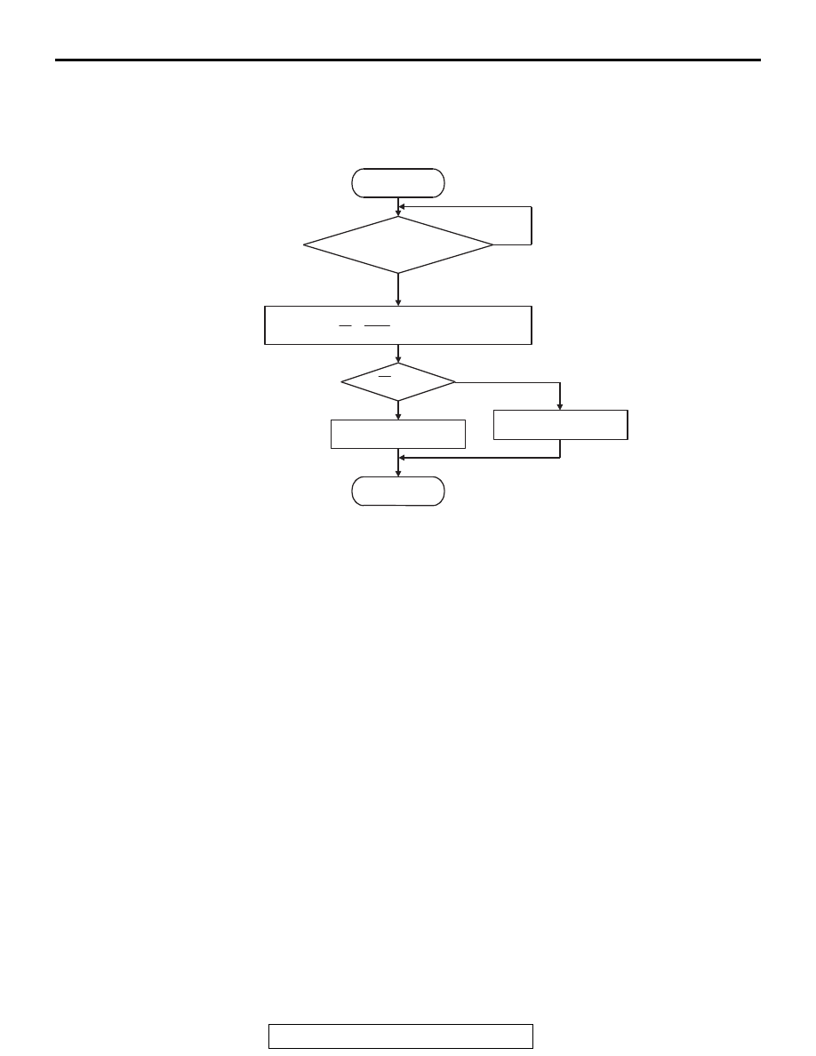
Logic Flow Chart
.
Check Conditions
• Engine speed is 3,500 r/min or lower.
• Accelerator pedal is depressed.
• Mass airflow is between 13 and 45 g/sec.
• More than 3.5 seconds have elapsed after the
above-mentioned three conditions have been
met.
• Intake air temperature is higher than −10° C
(14° F).
• Barometric pressure is higher than 76 kPa (22.4
in.Hg).
• Under the closed loop air/fuel ratio control.
• Vehicle speed is 1.5 km/h (1.0 mph) or more.
• The ECM monitors the maximum 5 times per
drive cycle under these conditions.
• Short-term fuel trim is higher than −
20 percent
and lower than +17 percent.
• The cumulative mass airflow is higher than 1,638
g.
Judgement Criterion
• When the monitoring for 10 seconds is carried
out 5 times, the frequency ratio of rear and front
signals is the specified value or more.
NOTE: The specified value varies depending on the
average air flow rate.
.
FAIL-SAFE AND BACKUP FUNCTION
• None
.
OBD-II DRIVE CYCLE PATTERN
Refer to Diagnostic Function − OBD-II Drive Cycle −
Pattern 3
.
.
TROUBLESHOOTING HINTS (The most
likely causes for this code to be set are:)
• Catalytic converter deteriorated.
• Heated oxygen sensor failed.
• Exhaust leak.
• ECM failed.
Start
Monitoring
conditions
Malfunction
Good
End
No
No
Yes
Yes
Rf > R0
Calculate average frequency
ratio (Rf = Fr/Ff) of specified times
R0: Average threshold value
AK604337