Mitsubishi Lancer Evolution X. Manual - part 336


  Index      Mitsubishi     Mitsubishi Lancer Evolution X GS41EVO - service repair manual 2008 year


Search            


Content   ..  334  335  336  337   ..


Mitsubishi Lancer Evolution X. Manual - part 336


MULTIPORT FUEL INJECTION (MFI) DIAGNOSIS

TSB Revision

MULTIPORT FUEL INJECTION (MFI)

13A-409

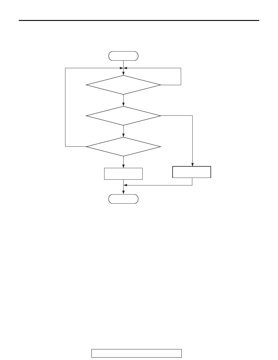
DTC SET CONDITIONS <Circuit continuity>

Logic Flow Chart

Check Condition

• Engine is being cranked.

or

• Engine speed is higher than 500 r/min excluding 

during cranking.

Judgement Criterion

• Exhaust camshaft position sensor output voltage 

has not changed (no pulse signal is input) for 2 
seconds.

.

Good

Malfunction

Output signal

changes

End

No

No

No

AK604334

Start

Yes

Yes

Yes

Monitoring
conditions

Continuous

failure for 2secs

MULTIPORT FUEL INJECTION (MFI) DIAGNOSIS

TSB Revision

MULTIPORT FUEL INJECTION (MFI)

13A-410

DTC SET CONDITIONS <Range/Performance problem  alignment>

Logic Flow Chart

Check Condition

• Engine is being cranked.

or

• Engine speed is higher than 500 r/min excluding 

during cranking.

Judgement Criterion

• Normal signal pattern has not been input for cyl-

inder identification from the crankshaft position 
sensor signal and exhaust camshaft position sen-
sor signal for 2 seconds.

.

FAIL-SAFE AND BACKUP FUNCTION

• Does not control variable valve timing (V.V.T.).

.

OBD-II DRIVE CYCLE PATTERN

Refer to Diagnostic Function − OBD-II Drive Cycle − 

Pattern 23 

P.13A-9

.

.

TROUBLESHOOTING HINTS (The most 
likely causes for this code to be set are: )

• Exhaust camshaft position sensor failed.
• Open or shorted exhaust camshaft position sen-

sor circuit, or harness damage, or connector 
damage.

• Exhaust camshaft failed.
• ECM failed. 

Good

Malfunction

Correct signal

pattem is detected

End

No

No

No

AK604335

Start

Yes

Yes

Yes

Monitoring
conditions

Continuous

failure for 2secs

MULTIPORT FUEL INJECTION (MFI) DIAGNOSIS

TSB Revision

MULTIPORT FUEL INJECTION (MFI)

13A-411

DIAGNOSIS

Required Special Tools:

• MB991709: Test Harness
• MB992110: Power Plant ECU Check Harness

STEP 1. Using the oscilloscope, check the exhaust 
camshaft position sensor.
(1) Disconnect the exhaust camshaft position sensor connector 

B-05, and connect test harness special tool (MB991709) 
between the separated connectors. (All terminals should be 
connected.)

(2) Connect the oscilloscope probe to the exhaust camshaft 

position sensor side connector terminal No. 3.
NOTE: When measuring with the ECM side connector, dis-
connect all ECM connectors. Connect the check harness 
special tool (MB992110) between the separated connec-
tors. Then connect the oscilloscope probe to the check har-
ness connector terminal No. 7.

(3) Start the engine and run at idle.

(4) Check the waveform.

• The waveform should show a pattern similar to the illus-

tration.

(5) Turn the ignition switch to the "LOCK" (OFF) position.
Q: Is the waveform normal?

YES : Go to Step 2.
NO :  Go to Step 4.

STEP 2. Check harness connector B-05 at exhaust 
camshaft position sensor and harness connector B-09 at 
ECM for damage.
Q: Is the harness connector in good condition?

YES : Go to Step 3.
NO :  Repair or replace it. Refer to GROUP 00E, Harness 

Connector Inspection 

P.00E-2

. Then go to Step 19.

AK604465

3

2

1

AE

Exhaust camshaft position
sensor connector

Oscilloscope

MB991709

AK704276 AB

2 engine revolutions

Normal waveform

5Volt

MULTIPORT FUEL INJECTION (MFI) DIAGNOSIS

TSB Revision

MULTIPORT FUEL INJECTION (MFI)

13A-412

STEP 3. Check the trouble symptoms.
(1) Carry out a test drive with the drive cycle pattern. Refer to 

Diagnostic Function − OBD-II Drive Cycle − Pattern 23 

P.13A-9

.

(2) Check the diagnostic trouble code (DTC).
Q: Is DTC P0365 set?

YES : Replace the ECM. When the ECM is replaced, 

register the ID code. Refer to GROUP 42B, ID Code 
Registration Necessity Judgment Table <Vehicles 
with KOS> 

P.42B-11

 or GROUP 42C, ID Codes 

Registration Judgment Table <Vehicles with WCM> 

P.42C-9

. Then go to Step 19.

NO :  It can be assumed that this malfunction is intermittent. 

Refer to GROUP 00, How to Use 
Troubleshooting/Inspection Service Points − How to 

Cope with Intermittent Malfunctions 

P.00-15

.

STEP 4. Check harness connector B-05 at exhaust 
camshaft position sensor for damage.
Q: Is the harness connector in good condition?

YES : Go to Step 5.
NO :  Repair or replace it. Refer to GROUP 00E, Harness 

Connector Inspection 

P.00E-2

. Then go to Step 19.

STEP 5. Measure the sensor supply voltage at exhaust 
camshaft position sensor connector B-05.
(1) Disconnect the connector B-05 and measure at the harness 

side.

(2) Turn the ignition switch to the "ON" position.
(3) Measure the voltage between terminal No. 3 and ground.

• Voltage should be between 4.9 and 5.1 volts.

(4) Turn the ignition switch to the "LOCK" (OFF) position.
Q: Is the measured voltage between 4.9 and 5.1 volts?

YES : Go to Step 9.
NO :  Go to Step 6.

STEP 6. Check harness connector B-09 at ECM for 
damage.
Q: Is the harness connector in good condition?

YES : Go to Step 7.
NO :  Repair or replace it. Refer to GROUP 00E, Harness 

Connector Inspection 

P.00E-2

. Then go to Step 19.

AK604205

1

2

3

AD

B-05 harness
connector:
component side 


Content   ..  334  335  336  337   ..