Mitsubishi Lancer Evolution X. Manual - part 332


  Index      Mitsubishi     Mitsubishi Lancer Evolution X GS41EVO - service repair manual 2008 year


Search            


Content   ..  330  331  332  333   ..


Mitsubishi Lancer Evolution X. Manual - part 332


MULTIPORT FUEL INJECTION (MFI) DIAGNOSIS

TSB Revision

MULTIPORT FUEL INJECTION (MFI)

13A-393

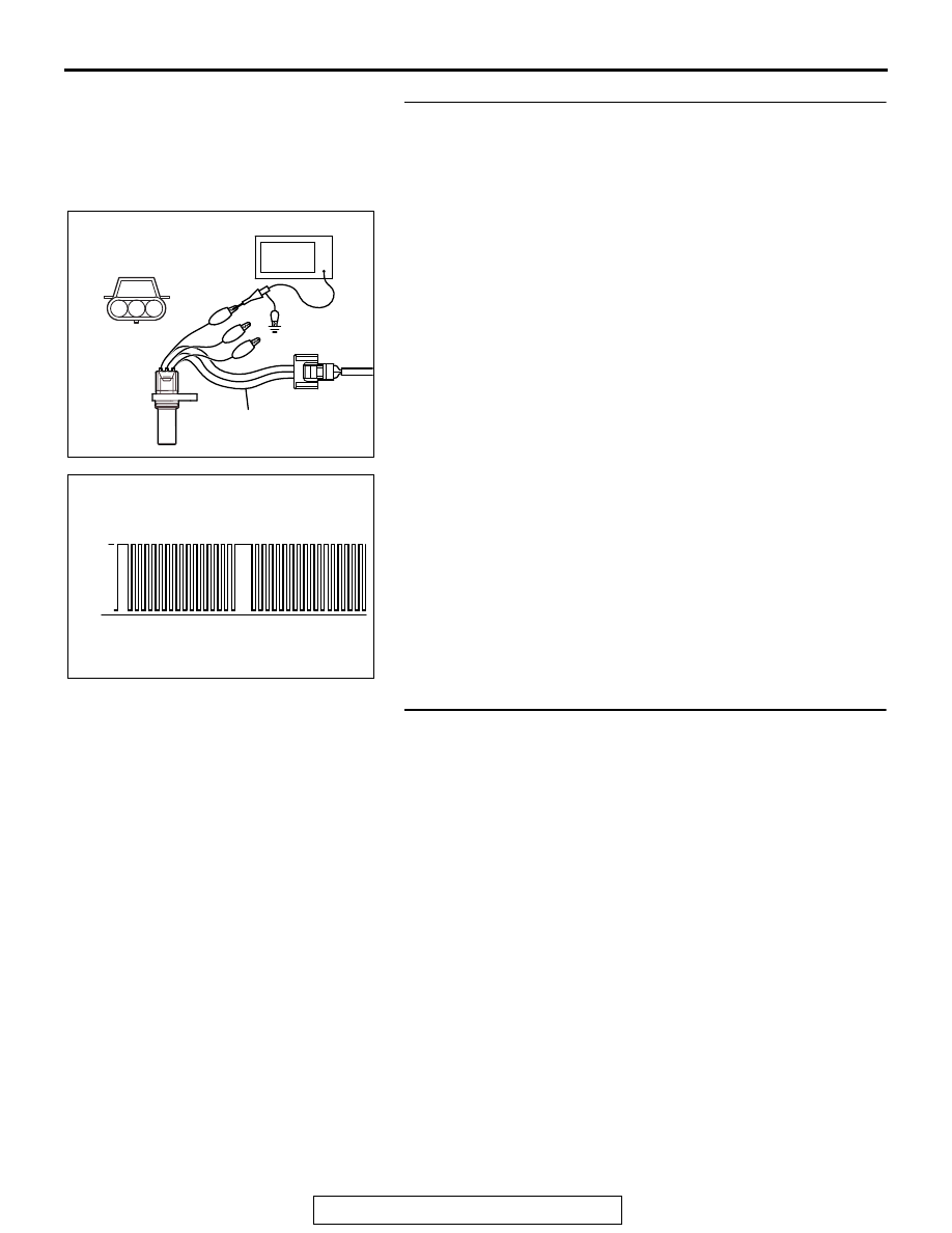
STEP 2. Using the oscilloscope, check the crankshaft 
position sensor.
(1) Disconnect the crankshaft position sensor connector B-13 

and connect the test harness special tool (MB991709) 
between the separated connectors.

(2) Connect the oscilloscope probe to terminal No. 3 of the 

crankshaft position sensor connector.
NOTE: When measuring with the ECM side connector, dis-
connect all ECM connectors. Connect the check harness 
special tool (MB992110) between the separated connec-
tors. Then connect the oscilloscope probe to the check har-
ness connector terminal No. 8.

(3) Start the engine and run at idle.

(4) Check the waveform.

• The waveform should show a pattern similar to the illus-

tration.

(5) Turn the ignition switch to the "LOCK" (OFF) position.
Q: Is the waveform normal?

YES : Go to Step 3.
NO :  Go to Step 5.

STEP 3. Check harness connector B-13 at the crankshaft 
position sensor and harness connector B-09 at ECM for 
damage.
Q: Is the harness connector in good condition?

YES : Go to Step 4.
NO :  Repair or replace it. Refer to GROUP 00E, Harness 

Connector Inspection 

P.00E-2

. Then go to Step 20.

AK704086

3

2

1

AB

Crankshaft position
sensor connector

Oscilloscope

MB991709

AK604547

5Volt

Normal waveform

AB

MULTIPORT FUEL INJECTION (MFI) DIAGNOSIS

TSB Revision

MULTIPORT FUEL INJECTION (MFI)

13A-394

STEP 4. Using scan tool MB991958, check data list item 2: 
Crankshaft Position Sensor.
(1) Turn the ignition switch to the "ON" position.
(2) Set scan tool MB991958 to the data reading mode for item 

2, Crankshaft Position Sensor.

• The tachometer and engine speed indicated on the scan 

tool should match.

(3) Turn the ignition switch to the "LOCK" (OFF) position.
Q: Is the sensor operating properly?

YES : It can be assumed that this malfunction is intermittent. 

Refer to GROUP 00, How to Use 
Troubleshooting/Inspection Service Points − How to 

Cope with Intermittent Malfunctions 

P.00-15

.

NO :  Replace the ECM. When the ECM is replaced, 

register the ID code. Refer to GROUP 42B, ID Code 
Registration Necessity Judgment Table <Vehicles 
with KOS> 

P.42B-11

 or GROUP 42C, ID Codes 

Registration Judgment Table <Vehicles with WCM> 

P.42C-9

. Then go to Step 20.

STEP 5. Check harness connector B-13 at the crankshaft 
position sensor for damage.
Q: Is the harness connector in good condition?

YES : Go to Step 6.
NO :  Repair or replace it. Refer to GROUP 00E, Harness 

Connector Inspection 

P.00E-2

. Then go to Step 20.

STEP 6. Measure the sensor supply voltage at crankshaft 
position sensor harness side connector B-13.
(1) Disconnect the connector B-13 and measure at the harness 

side.

(2) Turn the ignition switch to the "ON" position.
(3) Measure the voltage between terminal No. 3 and ground.

• Voltage should be between 4.9 and 5.1 volts.

(4) Turn the ignition switch to the "LOCK" (OFF) position.
Q: Is the measured voltage between 4.9 and 5.1 volts?

YES : Go to Step 10.
NO :  Go to Step 7.

AC608435

Data link connector

MB991827

MB991824

MB991910

AB

AK604197

1

2

3

AD

B-13 harness
connector:
component side 

MULTIPORT FUEL INJECTION (MFI) DIAGNOSIS

TSB Revision

MULTIPORT FUEL INJECTION (MFI)

13A-395

STEP 7. Check harness connector B-09 at ECM for 
damage.
Q: Is the harness connector in good condition?

YES : Go to Step 8.
NO :  Repair or replace it. Refer to GROUP 00E, Harness 

Connector Inspection 

P.00E-2

. Then go to Step 20.

STEP 8. Measure the sensor supply voltage at ECM 
connector B-09 by using power plant ECU check harness 
special tool MB992110.
(1) Disconnect all ECM connectors. Connect the power plant 

ECU check harness special tool MB992110 between the 
separated connectors.

(2) Disconnect the crankshaft position sensor connector B-13.
(3) Turn the ignition switch to the "ON" position.

(4) Measure the voltage between terminal No. 8 and ground.

• Voltage should be between 4.9 and 5.1 volts.

(5) Turn the ignition switch to the "LOCK" (OFF) position.
Q: Is the measured voltage between 4.9 and 5.1 volts?

YES : Repair harness wire between crankshaft position 

sensor connector B-13 (terminal No. 3) and ECM 
connector B-09 (terminal No. 8) because of open 
circuit. Then go to Step 20.

NO :  Go to Step 9.

AK604040

ECM

AB

Body side harness 

MB992110

AK604198

16 15 14 13 12 11 10 9 8 7 6 5 4 3

2

1

32 31 30 29 28 27 26 25 24 23 22 21 20 19 18 17

48 47 46 45 44 43 42 41 40 39 38 37 36 35 34 33

64 63 62 61 60 59 58 57 56 55 54 53 52 51 50 49

AB

Power plant ECU
check harness connector

MULTIPORT FUEL INJECTION (MFI) DIAGNOSIS

TSB Revision

MULTIPORT FUEL INJECTION (MFI)

13A-396

STEP 9. Check for short circuit to ground between 
crankshaft position sensor connector B-13 (terminal No. 3) 
and ECM connector B-09 (terminal No. 8).
Q: Is the harness wire in good condition?

YES : Replace the ECM. When the ECM is replaced, 

register the ID code. Refer to GROUP 42B, ID Code 
Registration Necessity Judgment Table <Vehicles 
with KOS> 

P.42B-11

 or GROUP 42C, ID Codes 

Registration Judgment Table <Vehicles with WCM> 

P.42C-9

. Then go to Step 20.

NO :  Repair it. Then go to Step 20.

STEP 10. Measure the power supply voltage at crankshaft 
position sensor harness side connector B-13.
(1) Disconnect the connector B-13 and measure at the harness 

side.

(2) Turn the ignition switch to the "ON" position.
(3) Measure the voltage between terminal No. 1 and ground.

• Voltage should be between 4.9 and 5.1 volts.

(4) Turn the ignition switch to the "LOCK" (OFF) position.
Q: Is the measured voltage between 4.9 and 5.1 volts?

YES : Go to Step 13.
NO :  Go to Step 11.

STEP 11. Check harness connector B-09 at ECM for 
damage.
Q: Is the harness connector in good condition?

YES : Go to Step 12.
NO :  Repair or replace it. Refer to GROUP 00E, Harness 

Connector Inspection 

P.00E-2

. Then go to Step 20.

STEP 12. Check for open circuit and short circuit to 
ground between crankshaft position sensor connector 
B-13 (terminal No. 1) and ECM connector B-09 (terminal 
No. 9).
Q: Is the harness wire in good condition?

YES : Replace the ECM. When the ECM is replaced, 

register the ID code. Refer to GROUP 42B, ID Code 
Registration Necessity Judgment Table <Vehicles 
with KOS> 

P.42B-11

 or GROUP 42C, ID Codes 

Registration Judgment Table <Vehicles with WCM> 

P.42C-9

. Then go to Step 20.

NO :  Repair it. Then go to Step 20.

AK604199

1

2

3

AD

B-13 harness
connector:
component side 


Content   ..  330  331  332  333   ..