Mitsubishi Lancer Evolution X. Manual - part 331


  Index      Mitsubishi     Mitsubishi Lancer Evolution X GS41EVO - service repair manual 2008 year


Search            


Content   ..  329  330  331  332   ..


Mitsubishi Lancer Evolution X. Manual - part 331


MULTIPORT FUEL INJECTION (MFI) DIAGNOSIS

TSB Revision

MULTIPORT FUEL INJECTION (MFI)

13A-389

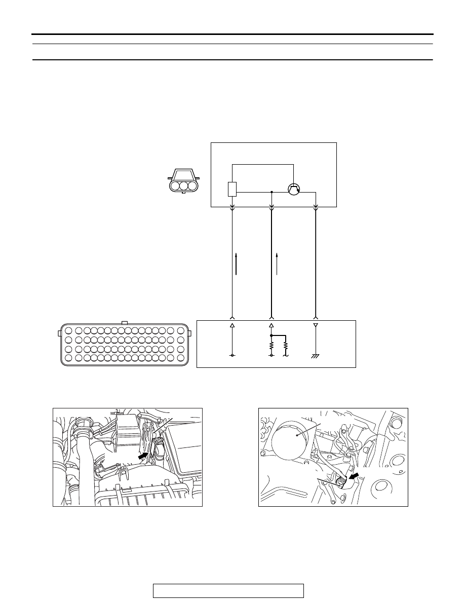
DTC P0335: Crankshaft Position Sensor Circuit

.

CIRCUIT OPERATION

• The crankshaft position sensor power is supplied 

from the ECM (terminal No. 9).

• Terminal No. 2 of the crankshaft position sensor 

is grounded with ECM (terminal No. 24).

• A 5-volt voltage is applied on the crankshaft posi-

tion sensor output terminal (terminal No. 3) from 
the ECM (terminal No. 8). The crankshaft position 
sensor generates a pulse signal when the output 
terminal is opened and grounded.

.

AK604245

1

2

3 4 5 6 7 8 9 10 11 12 13 14 15 16

17 18 19 20 21 22 23 24 25 26 27 28 29 30 31 32

33 34 35 36 37 38 39 40 41 42 43 44 45 46 47 48

49 50 51 52 53 54 55 56 57 58 59 60 61 62 63 64

3

2

1

CRANKSHAFT POSITION SENSOR CIRCUIT

CRANKSHAFT
POSITION SENSOR

B-13

(MU802348)

B-09

RED-GREEN

RED-BLUE

YELLO

W

-VIOLET

9

1

8

3

24

2

5 V

5 V

AD

ENGINE
CONTROL
MODULE

AK704227

Connector: B-09

ECM

B-09 (GR)

AB

AK704272

Engine oil
filter

AB

Crankshaft
position sensor

Connector: B-13

B-13 (GR)

MULTIPORT FUEL INJECTION (MFI) DIAGNOSIS

TSB Revision

MULTIPORT FUEL INJECTION (MFI)

13A-390

TECHNICAL DESCRIPTION

• The crankshaft position sensor detects the crank 

angle (position) of each cylinder, and converts 
that data to pulse signals, then which are input to 
the ECM.

• When the engine is running, the crankshaft posi-

tion sensor outputs a pulse signal.

• The ECM checks whether pulse signal is input 

while the engine is cranking.

.

DESCRIPTIONS OF MONITOR METHODS

• Crankshaft position sensor signal does not 

change.

• Crankshaft position sensor signal is not normal 

pattern.

.

MONITOR EXECUTION

Continuous

.

MONITOR EXECUTION CONDITIONS 
(Other monitor and Sensor)

Other Monitor (There is no temporary DTC stored 

in memory for the item monitored below)

• Not applicable

Sensor (The sensor below is determined to be 

normal)

• Not applicable

.

DTC SET CONDITIONS <Circuit continuity>

Logic Flow Chart

Check Condition

• Engine is being cranked.

or

• Engine speed is higher than 500 r/min excluding 

during cranking.

Judgement Criterion

• Crankshaft position sensor output voltage has not 

changed (no pulse signal is input) for 2 seconds.

.

Good

Malfunction

Output signal

changes

End

No

No

No

AK604334

Start

Yes

Yes

Yes

Monitoring
conditions

Continuous

failure for 2secs

MULTIPORT FUEL INJECTION (MFI) DIAGNOSIS

TSB Revision

MULTIPORT FUEL INJECTION (MFI)

13A-391

DTC SET CONDITIONS <Range/Performance problem  alignment>

Logic Flow Chart

Check Condition

• Engine is being cranked.

or

• Engine speed is higher than 500 r/min excluding 

during cranking.

Judgement Criterion

• Normal signal pattern has not been input for cyl-

inder identification from the crankshaft position 
sensor signal and camshaft position sensor sig-
nal for 2 seconds.

.

FAIL-SAFE AND BACKUP FUNCTION

• None

.

OBD-II DRIVE CYCLE PATTERN

Refer to Diagnostic Function − OBD-II Drive Cycle − 

Pattern 23 

P.13A-9

.

.

TROUBLESHOOTING HINTS (The most 
likely causes for this code to be set are:)

• Crankshaft position sensor failed.
• Open or shorted crankshaft position sensor cir-

cuit, or harness damage, or connector damage.

• Crankshaft position sensing ring failed
• ECM failed.

Good

Malfunction

Correct signal

pattem is detected

End

No

No

No

AK604335

Start

Yes

Yes

Yes

Monitoring
conditions

Continuous

failure for 2secs

MULTIPORT FUEL INJECTION (MFI) DIAGNOSIS

TSB Revision

MULTIPORT FUEL INJECTION (MFI)

13A-392

DIAGNOSIS

Required Special Tools:

• MB991958: Scan Tool (M.U.T.-III Sub Assembly)

• MB991824: V.C.I.
• MB991827: USB Cable
• MB991910: Main Harness A

• MB991709: Test Harness
• MB992110: Power Plant ECU Check Harness

STEP 1. Using scan tool MB991958, check data list item 2: 
Crankshaft Position Sensor.

CAUTION

To prevent damage to scan tool MB991958, always turn the 
ignition switch to the "LOCK" (OFF) position before con-
necting or disconnecting scan tool MB991958.
(1) Connect scan tool MB991958 to the data link connector.
(2) Start the engine and run at idle.
(3) Set scan tool MB991958 to the data reading mode for item 

2, Crankshaft Position Sensor.

• The tachometer and engine speed indicated on the scan 

tool should match.

(4) Turn the ignition switch to the "LOCK" (OFF) position.
Q: Is the sensor operating properly?

YES : It can be assumed that this malfunction is intermittent. 

Refer to GROUP 00, How to Use 
Troubleshooting/Inspection Service Points − How to 

Cope with Intermittent Malfunctions 

P.00-15

.

NO :  Go to Step 2.

AC608435

Data link connector

MB991827

MB991824

MB991910

AB


Content   ..  329  330  331  332   ..