Mitsubishi Lancer Evolution X. Manual - part 307
MULTIPORT FUEL INJECTION (MFI) DIAGNOSIS
TSB Revision
MULTIPORT FUEL INJECTION (MFI)
13A-293
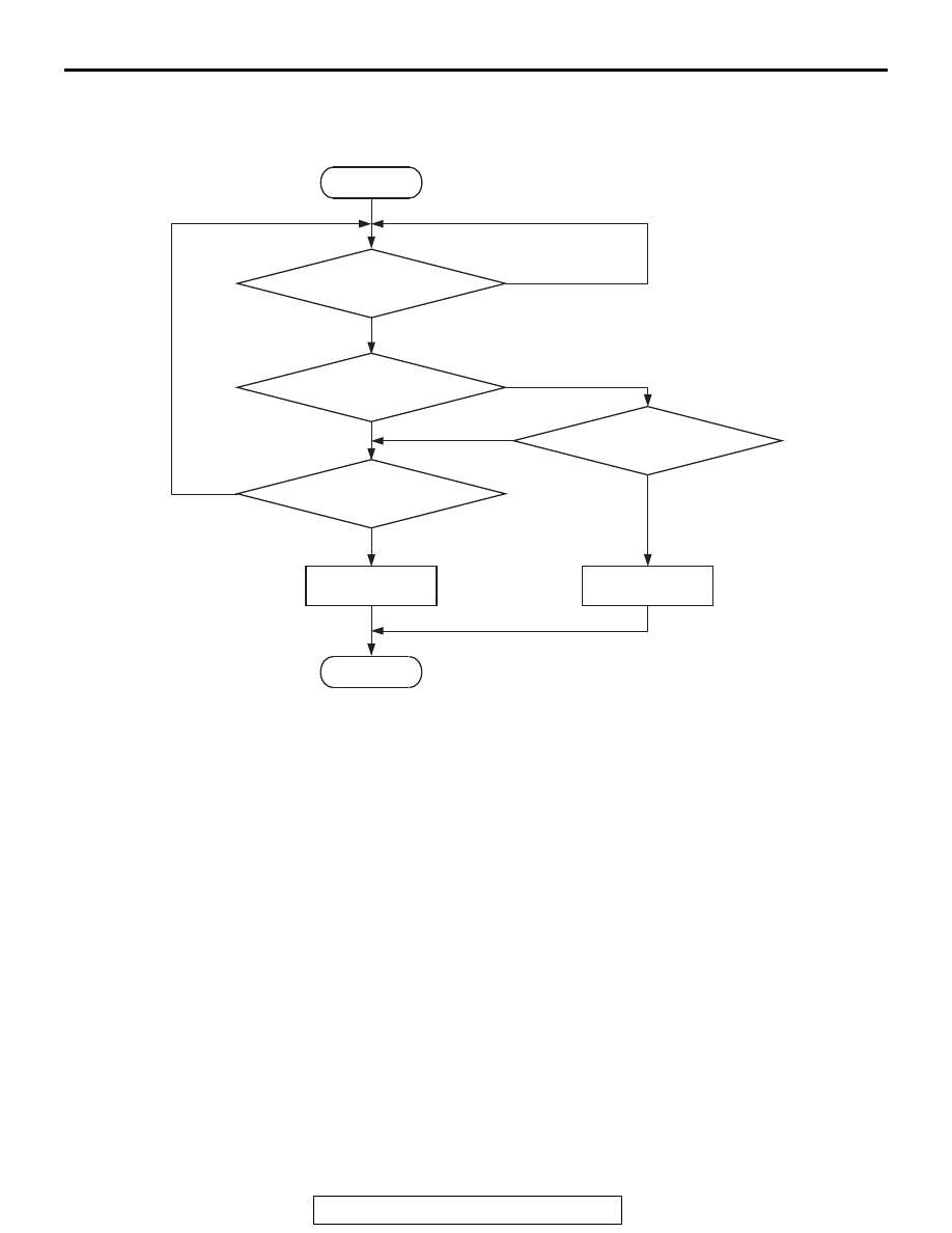
DTC SET CONDITIONS
Logic Flow Chart
.
Check Condition
• 2 seconds or more have passed since the engine
starting sequence was completed.
Judgement Criterion
• Sensor output voltage has continued to be 4.6
volts or higher for 2 seconds.
.
FAIL-SAFE AND BACKUP FUNCTION
• None
.
OBD-II DRIVE CYCLE PATTERN
Refer to Diagnostic Function − OBD-II Drive Cycle −
Pattern 23
.
.
TROUBLESHOOTING HINTS (The most
likely causes for this code to be set are:)
• Fuel tank temperature sensor failed.
• Open fuel tank temperature sensor circuit, har-
ness damage, or connector damage.
• ECM failed.
DIAGNOSIS
Required Special Tools:
• MB991958: Scan Tool (M.U.T.-III Sub Assembly)
• MB991824: V.C.I.
• MB991827: USB Cable
• MB991910: Main Harness A
• MB992110: Power Plant ECU Check Harness
AK700478
Good
Malfunction
End
No
No
No
No
Yes
Yes
Yes
Yes
Continuous
failure for 2secs
Monitoring
conditions
Start
Output voltage
< 0.1V
Output voltage
> 4.6V