Mitsubishi Lancer Evolution X. Manual - part 304
MULTIPORT FUEL INJECTION (MFI) DIAGNOSIS
TSB Revision
MULTIPORT FUEL INJECTION (MFI)
13A-281
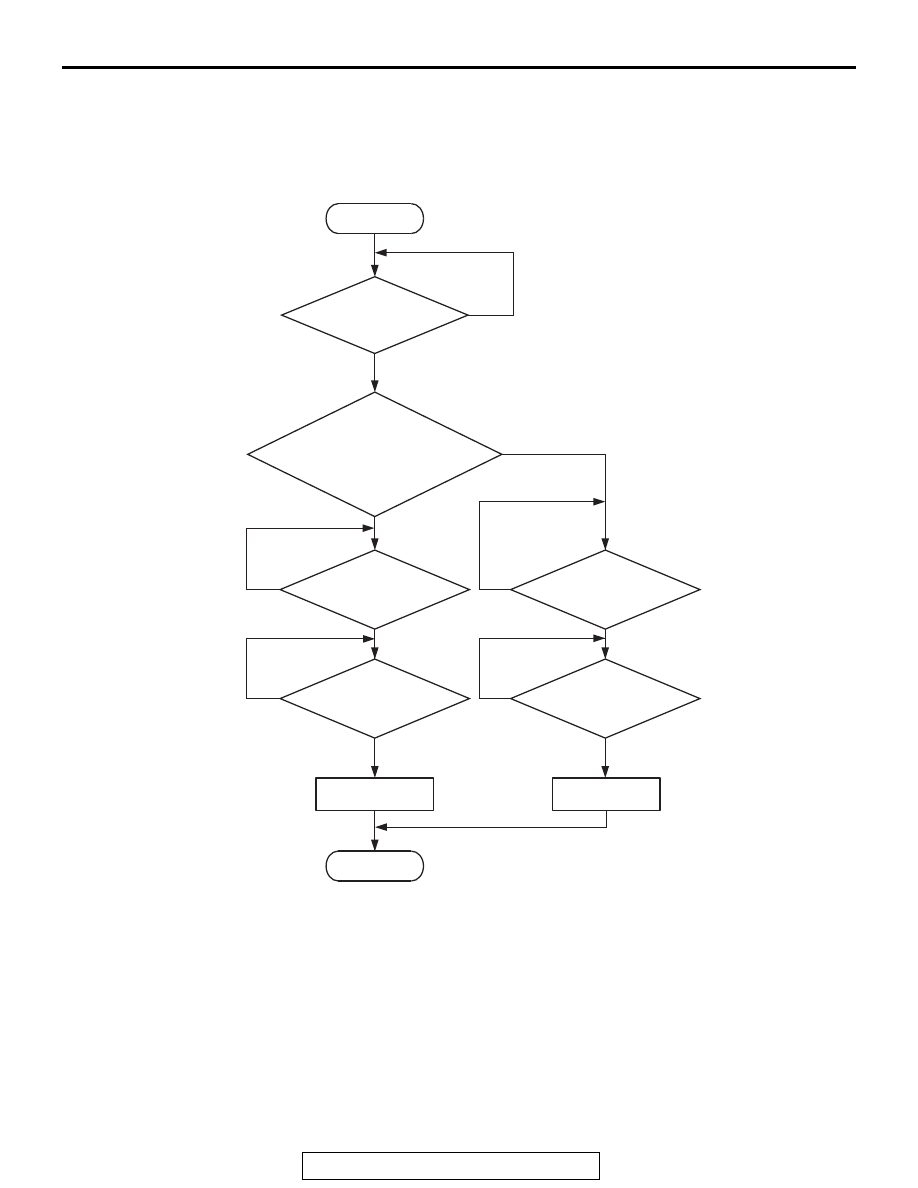
DTC SET CONDITIONS
Logic Flow Chart
.
Check Conditions
• The engine coolant temperature − intake air tem-
perature is 5° C (9° F) or less when the engine is
started.
• The engine coolant temperature is between
−10° C (14° F) and 36° C (97° F) when the engine
is started.
• The engine coolant temperature is 60° C (140° F)
or higher.
• Maximum vehicle speed is higher than 30 km/h
(19 mph) after the engine starting sequence has
been completed.
Judgement Criterion
• The fuel tank temperature − engine coolant tem-
perature is 15° C (27° F) or more when the engine
is started.
No
No
No
No
End
No
No
Malfunction
Good
“Fuel temp. at
engine start”-
“engine coolant temp. at
engine start”
> 15˚C (27˚F)
Engine
coolant temp.
> =60˚C (140˚F)
Engine
coolant temp.
> =60˚C (140˚F)
Max.
vehicle speed
> 30km/h (19mph)
Max.
vehicle speed
> 30km/h (19mph)
AK700114
Start
Yes
Yes
Yes
Yes
Yes
Yes
Monitoring
conditions