Mitsubishi Lancer Evolution X. Manual - part 303


  Index      Mitsubishi     Mitsubishi Lancer Evolution X GS41EVO - service repair manual 2008 year


Search            


Content   ..  301  302  303  304   ..


Mitsubishi Lancer Evolution X. Manual - part 303


MULTIPORT FUEL INJECTION (MFI) DIAGNOSIS

TSB Revision

MULTIPORT FUEL INJECTION (MFI)

13A-277

STEP 4. Using scan tool MB991958, check data list item 8: 
Manifold Absolute Pressure Sensor.
(1) Turn the ignition switch to the "ON" position.
(2) Set scan tool MB991958 to the data reading mode for item 

8, Manifold Absolute Pressure Sensor.

• When altitude is 0 m (0 foot), 101 kPa (29.8 in.Hg).
• When altitude is 600 m (1,969 feet), 95 kPa (28.1 in.Hg).
• When altitude is 1,200 m (3,937 feet), 88 kPa (26.0 

in.Hg).

• When altitude is 1,800 m (5,906 feet), 81 kPa (23.9 

in.Hg).

(3) Start the engine.

• When the engine is idling, 31 − 45 kPa (9.1 − 13.3 in.Hg).
• When the engine is suddenly revved, manifold absolute 

pressure varies.

(4) Turn the ignition switch to the "LOCK" (OFF) position.
Q: Is the sensor operating properly?

YES : Go to Step 5.
NO :  Refer to DTC P0106 − Manifold Absolute Pressure 

Circuit Range/Performance Proble

P.13A-144

, DTC 

P0107 − Manifold Absolute Pressure Circuit Low Input 

P.13A-153

, DTC P0108 − Manifold Absolute Pressure 

Circuit High Input 

P.13A-161

.

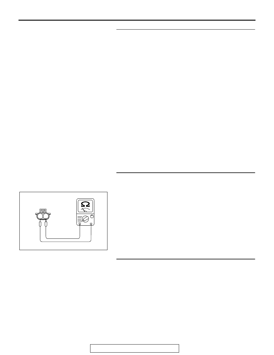
STEP 5. Check the injector.
(1) Disconnect the injector connector B-101, B-102, B-103 and 

B-104.

(2) Measure the resistance between each injector side 

connector terminal No. 1 and No. 2.

Standard value: 10.5  13.5 Ω [at 20° C (68° F)]

Q: Is the measured resistance between 10.5 and 13.5 Ω [at 

20° C (68° F)]?
YES : 
Go to Step 6.
NO :  Replace the injector. Then go to Step 8.

STEP 6. Check the fuel pressure.
Refer to On-vehicle Service − Fuel Pressure Test 

P.13A-865

.

Q: Is the fuel pressure normal?

YES : Go to Step 7.
NO :  Repair it. Then go to Step 8.

AK604038

1 2

AB

Injector side
connector

MULTIPORT FUEL INJECTION (MFI) DIAGNOSIS

TSB Revision

MULTIPORT FUEL INJECTION (MFI)

13A-278

STEP 7. Replace the injector.
(1) Replace the injector.
(2) Carry out a test drive with the drive cycle pattern. Refer to 

Diagnostic Function − OBD-II Drive Cycle − Pattern 21 

P.13A-9

.

(3) Check the diagnostic trouble code (DTC).
Q: Is DTC P0172 set?

YES : Replace the ECM. When the ECM is replaced, 

register the ID code. Refer to GROUP 42B, ID Code 
Registration Necessity Judgment Table <Vehicles 
with KOS> 

P.42B-11

 or GROUP 42C, ID Codes 

Registration Judgment Table <Vehicles with WCM> 

P.42C-9

. Then go to Step 8.

NO :  The inspection is complete.

STEP 8. Test the OBD-II drive cycle.
(1) Carry out a test drive with the drive cycle pattern. Refer to 

Diagnostic Function − OBD-II Drive Cycle − Pattern 21 

P.13A-9

.

(2) Check the diagnostic trouble code (DTC).
Q: Is DTC P0172 set?

YES : Retry the troubleshooting.
NO :  The inspection is complete.

MULTIPORT FUEL INJECTION (MFI) DIAGNOSIS

TSB Revision

MULTIPORT FUEL INJECTION (MFI)

13A-279

DTC P0181: Fuel Tank Temperature Sensor Circuit Range/Performance

1

2 3

4

5

AK604240

71 72 73 74 75 76 77 78 79 80 81 82

83 84 85 86 87 88 89 90 91 92 93 94

95 96 97 98 99

100 101 102 103 104

112 113 114

109

108

107

110 111

115 116

106

105

118

117

2

8

7

6

5

4

3

11

21

20

19

18

17

16

15

14

13

12

9

22

1

10

AC

FUEL TANK TEMPERATURE  SENSOR  CIRCUIT

6

3

2

1

BLA

CK

D-22

(MU802058)

115

FUEL TANK TEMPERATURE
SENSOR (INTEGRATED IN FUEL
PUMP MODULE)

5 V

WHITE-BLA

CK

WHITE-BLA

CK

B-10

C-47

FROM
COMBNATION
METER

ENGINE
CONTROL
MODULE

AK704235 AB

Connector: B-10

ECM

B-10 (GR)

AK704252

Connector: C-47

C-47

AB

MULTIPORT FUEL INJECTION (MFI) DIAGNOSIS

TSB Revision

MULTIPORT FUEL INJECTION (MFI)

13A-280

.

CIRCUIT OPERATION

• 5-volt voltage is applied to the fuel tank tempera-

ture sensor output terminal (terminal No. 3) from 
the ECM (terminal No. 115) via the resistor in the 
ECM.

• The fuel tank temperature sensor output voltage 

increases when the resistance increases and 
decreases when the resistance decreases. The 
ground terminal (terminal No. 1) is grounded to 
the vehicle body.

.

TECHNICAL DESCRIPTION

• The fuel tank temperature sensor converts the 

fuel tank temperature to a voltage.

• The ECM detects the fuel tank temperature with 

this output voltage.

.

DESCRIPTIONS OF MONITOR METHODS

Fuel tank temperature at engine start is higher than 

engine coolant temperature at engine start by 
specified value when engine is cold start condi-
tion.

.

MONITOR EXECUTION

Continuous

.

MONITOR EXECUTION CONDITIONS 
(Other monitor and Sensor)

Other Monitor (There is no temporary DTC stored 

in memory for the item monitored below)

• Not applicable

Sensor (The sensor below is determined to be 

normal)

• Engine coolant temperature sensor
• Intake air temperature sensor

.

AK704253 AB

Fuel pump module (incorporating 
fuel level sensor (main) and 
fuel tank temperature sensor)

Connector: D-22

D-22 (GR)


Content   ..  301  302  303  304   ..