Mitsubishi Lancer Evolution X. Manual - part 230


  Index      Mitsubishi     Mitsubishi Lancer Evolution X GS41EVO - service repair manual 2008 year


Search            


Content   ..  228  229  230  231   ..


Mitsubishi Lancer Evolution X. Manual - part 230


STEERING SHAFT

TSB Revision

POWER STEERING

37-35

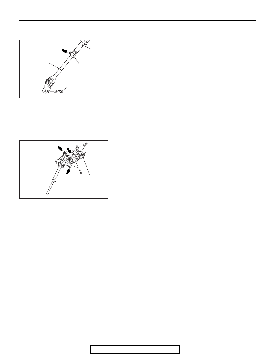
<<C>> STEERING COLUMN SHAFT ASSEMBLY 
DISCONNECTION

1. Remove the steering column bolt connecting the steering 

gear to the steering column assembly.

2. Disconnect the steering gear from the steering column 

assembly while sliding the shaft A to the shaft B with the clip 
claw as shown in the figure is pinched.

3. Remove the steering column mounting bolt.

INSTALLATION SERVICE POINTS

.

>>A<< STEERING COLUMN SHAFT ASSEMBLY 
INSTALLATION

1. Ensure that the tilt lever is in the lock position.
2. Temporarily tighten the mounting bolts in the order of a, b, 

and c, and then tighten them in the order of c, b, and a to the 
specified torque.

Tightening torque a: 28 ± 7 N⋅ m (21 ± 5 ft-lb)

Tightening torque b,c: 12 ± 3 N⋅ m (106 ± 27 in-lb)

.

AC609625 AB

Shaft B

Shaft A

Steering
column bolt

Clip

Claw

AC705591

b

a

c

AB

Tilt lever

STEERING SHAFT

TSB Revision

POWER STEERING

37-36

>>B<< STEERING COLUMN BOLT (STEERING 
COLUMN SHAFT ASSEMBLY AND STEERING 
GEAR & LINKAGE CONNECTION) INSTALLATION

1. While sliding shaft A from shaft B with the clip claw as 

shown in the figure being pinched, connect the steering 
column shaft assembly and the steering gear and linkage.

2. Insert the steering column bolt from the no tapped bolt hole, 

and tighten it to the specified torque.

Tightening torque : 20 ± 5 N⋅ m (15 ± 4 ft-lb)

DISASSEMBLY AND ASSEMBLY

M1372011700548

AC700698 AC

Yoke steering column
assembly

Bolt hole
(Tapped hole)

Bolt hole
(No tapped hole)

Steering column bolt

Clip

Claw

Steering
column bolt

Shaft B

Shaft A

AC613519 AC

N

1

2

4

3

Disassembly steps 

<<

A

>>

>>

A

<<

1.

Steering lock bolt

>>

A

<<

2.

Steering lock bracket

>>

A

<<

3.

Steering lock cylinder 
assembly

4.

Steering column shaft 
assembly

Disassembly steps 

STEERING SHAFT

TSB Revision

POWER STEERING

37-37

DISASSEMBLY SERVICE POINT

.

<<A>> STEERING LOCK BOLT REMOVAL

1. Use a drill to make a hole just deeply enough for the tap to 

stand on the steering lock bolt.

2. Use a left-hand thread tap to remove the steering lock bolt.

ASSEMBLY SERVICE POINT

.

>>A<< STEERING LOCK CYLINDER ASSEM-
BLY/STEERING LOCK BRACKET/STEERING 
LOCK BOLT INSTALLATION

1. When installing the steering lock assembly to the steering 

column shaft assembly, temporarily assemble the steering 
lock assembly while aligning it with the boss on the column.

2. Make sure that the steering lock operates normally, and then 

tighten the steering lock bolt until its head is broken off.

AC609628AB

Steering lock
assembly

Steering
lock bolt

Steering lock
assembly

Reverse screw tap

ACX01139 AB

POWER STEERING GEAR BOX AND LINKAGE

TSB Revision

POWER STEERING

37-38

POWER STEERING GEAR BOX AND LINKAGE

REMOVAL AND INSTALLATION

M1372010901779

CAUTION

• Before removing the steering wheel assembly and driver's air bag module, always refer to GROUP 

52B  Service Precaution

P.52B-24

 and Driver’s Air bag Module and Clock Spring 

P.52B-413

. Also

position the front wheels in a straight ahead direction. If you fail to do this, clock spring for SRS 
may get damage, making the SRS (air bag) inoperative, and it may cause a serious injury to the 
driver.

• *: Indicates the bolts and nuts with friction coefficient stabilizer. In removal, ensure there is no 

damage, clean dust and soiling from bearing and thread surfaces, and tighten them to the speci-
fied torque.

• After installation, perform a calibration for the ASC-ECU to learn the steering wheel sensor neutral 

point. (Refer to GROUP 35C  On-vehicle Service  Steering Wheel Sensor Calibration 

P.35C-289

).

Pre-removal Operation
• Power Steering Fluid Draining  (Refer to 

P.37-24

).

• Steering Wheel Assembly and Air Bag Module Removal 

(Refer to 

P.37-29

).

• Steering Shaft Cover Removal (Refer to 

P.37-33

).

• Engine Room Under Cover Front (A, B), Engine Room 

Side Cover, Front Floor Panel Rear Removal (Refer to 

GROUP 51 − Under Cover 

P.51-15

).

• Lower Arm Removal (Refer to GROUP 33 − Lower Arm 

P.33-15

).

• Centermember and Front Roll Stopper Assembly 

Removal (Refer to GROUP 32 − Engine Roll Stopper and 

Centermember 

P.32-10

).

Post-installation Operation
• Centermember and Front Roll Stopper Assembly Installa-

tion (Refer to GROUP 32 − Engine Roll Stopper and Cen-

termembe

P.32-10

).

• Lower Arm Installation (Refer to GROUP 33 − Lower Arm 

P.33-15

).

• Engine Room Under Cover Front (A, B), Engine Room 

Side Cover Installation (Refer to GROUP 51 − Under 

Cover 

P.51-15

).

• Steering Shaft Cover Removal (Refer to 

P.37-33

).

• Steering Wheel Assembly and Air Bag Module Installation 

(Refer to 

P.37-29

).

• Using your Fingers, Press the Dust Cover of Joints to 

Check for a Crack or Damage.

• Power Steering Fluid Filling (Refer to 

P.37-24

).

• Air Bleeding of Power Steering Fluid (Refer to 

P.37-25

).

• Steering Wheel at Straight-ahead Position Check


Content   ..  228  229  230  231   ..