Mitsubishi Lancer Evolution X. Manual - part 228


  Index      Mitsubishi     Mitsubishi Lancer Evolution X GS41EVO - service repair manual 2008 year


Search            


Content   ..  226  227  228  229   ..


Mitsubishi Lancer Evolution X. Manual - part 228


ON-VEHICLE SERVICE

TSB Revision

POWER STEERING

37-27

8. Turn the steering wheel all the way to the left or right; then 

check whether or not the retention hydraulic pressure is the 
standard value.

Standard value: 8.1  8.8 MPa (1,175  1,276 psi)

9. If not the standard value, overhaul the steering gear. 

Remeasure fluid pressure.

10. Remove the special tools MB991548, MB990662 and 

MB991549, and then tighten the pressure hose to the 
specified torque.

Tightening torque: 57 ± 7 N⋅ m (42 ± 5 ft-lb)

11. Bleed the system (Refer to 

P.37-25

).

POWER STEERING PRESSURE SWITCH CHECK

M1372007200722

Required Special Tools:

• MB990662: Power Steering Oil Pressure Gauge
• MB991548: Oil Pressure Gauge Adapter A (Pump Side)
• MB991549: Oil Pressure Gauge Adapter B (Hose Side)

1. Disconnect the pressure hose from the oil pump, and then 

connect the special tools MB991548, MB990662 and 
MB991549.

2. Bleed air, and then turn the steering wheel several times 

while the vehicle is not moving so that the temperature of 
the fluid rises to approximately 50° C − 60° C (122° F − 

140° F).

3. The engine should be idling.
4. Disconnect the connector for the oil pressure switch, and 

place an ohmmeter at the switch.

5. Gradually close the shut-off valve of the pressure gauge and 

increase the hydraulic pressure, then check whether or not 
the hydraulic pressure that activates the switch is the 
standard value.

2.5  3.0 MPa (363  435 psi)

6. Gradually open the shut-off valve and reduce the hydraulic 

pressure; then check whether or not the hydraulic pressure 
that deactivates the switch is the standard value.

1.5  3.0 MPa (218  435 psi)

7.  Remove special tools MB991548, MB990662 and 

MB991549, connect the pressure hose to the oil pump, and 
then tighten the eye bolt to the specified torque.

Tightening torque: 57 ± 7 N⋅ m (42 ± 5 ft-lb)

8. Bleed the system. (Refer to 
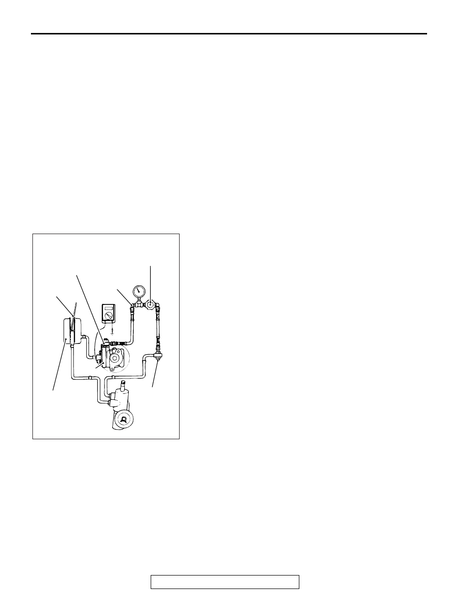
P.37-25

).

ACX01134 AI

Oil
 pump

Shut-off
valve

Oil reservoir

Power steering 
oil pressure 
gauge adapter
(MB991548)

Oil pressure 
gauge adapter A
(MB991548)

Oil pressure 
gauge adapter 
B (MB991549)

Temperature 
gauge

ON-VEHICLE SERVICE

TSB Revision

POWER STEERING

37-28

STEERING COLUMN SHAFT ASSEMBLY SHOCK 
ABSORBING MECHANISM CHECK

M1372013500647

.

WARNING

If the vehicle continues to be driven after the colli-
sion absorbing mechanism has operated, the 
steering column shaft may be damaged while it is 
in use.

If there is a slack in the mounting base, do not 
attempt to repair it. Replace the steering column 
shaft assembly.

If a collision accident occurs or severe impact is applied on the 
steering wheel, the collision energy absorbing mechanism may 
have operated. Once the mechanism has operated, it will be 
inoperative even if it has suffered no apparent damage. Deter-
mine if the steering column shaft can be reused by the following 
procedure. If the collision energy absorbing mechanism has 
already operated, replace the steering shaft assembly (Refer to 

P.37-33

). If any excessive radial freeplay on the steering wheel 

is found with the tilt lever in the lock position, always inspect the 
steering shaft assembly.

.

Inspection procedure:
1. Remove the lower and upper column covers.

CAUTION

After inspection, do not release the tilt lever until the steer-
ing shaft assembly has been installed.
2. Ensure that the tilt lever is in the lock position.
3. Loosen the two upper steering column mounting bolts by 

two turns.

4. Hold the one-way capsules as shown, and then try to rock 

them. If there is a slack in either of the capsules, replace the 
steering column shaft assembly (Refer to 

P.37-33

).

Reference:
The mounting base is fixed to the column bracket with the 
rivet. Before the collision energy absorbing mechanism 
operates, the column bracket is secured to the mounting 
base. After operation, the rivet will break off causing a slack.

CAUTION

• Be careful that nothing is pinched between the mount-

ing base and the body.

• After inspection, do not release the tilt lever until the 

steering shaft assembly has been installed.

5. After inspection, if there is no fault, tighten the two steering 

column upper side mounting bolts (2 bolts) to the specified 
torque.

Tightening torque: 12 ± 3 N⋅ m (106 ± 27 in-lb)

AC609398 AB

One-way capsule

Steering
column
assembly

Tilt lever

Steering column
mounting bolt

One-way capsule

STEERING WHEEL

TSB Revision

POWER STEERING

37-29

STEERING WHEEL

REMOVAL AND INSTALLATION

M1372011401498

CAUTION

• Before removing the steering wheel assembly and driver's air bag module, always refer to GROUP 

52B  Service Precautions 

P.52B-24

 and Driver’s Air bag Module and Clock Spring 

P.52B-413

.

• After removing the steering wheel, always perform a calibration for the ASC-ECU to learn the 

steering wheel sensor neutral point. (Refer to GROUP 35C  On-vehicle Service, Steering Wheel 

Sensor Calibration 

P.35C-289

.)

Pre-removal Operation
Steering Wheel at Straight-ahead Position Check

Post-installation Operation
• Steering Wheel at Straight-ahead Position Check
• Steering Wheel looseness Check

AC708304 AB

1

7

18

8

2

3

4

1

9

44 ± 11 N·m
32 ± 8 ft-lb

Craw

5

10

8

2

3

4

6

11

13

16

17

18

9.5 ± 2.5 N·m
84 ± 22 in-lb 

14

15

Craw

12

9.5 ± 2.5 N·m
84 ± 22 in-lb 

2.5 ± 0.5 N·m
22 ± 4 in-lb 

Removal steps 

<<

A

>>

1. Cover

>>

B

<<

2. Horn connector connection

>>

B

<<

3. Steering switch connector 

connection

<<

B

>>

>>

B

<<

4. Driver’s air bag module 

connector connection

5. Steering wheel voice control 

switch cover <Vehicles with 
steering wheel voice control 
switch>

6. Steering wheel voice control 

switch connector connection 
<Vehicles with steering wheel 
voice control switch>

7. Steering wheel voice control 

switch <Vehicles with steering 
wheel voice control switch>

<<

C

>>

>>

A

<<

8. Driver’s air bag module
9. Flange nut
10. Lower cover

Removal steps (Continued)

STEERING WHEEL

TSB Revision

POWER STEERING

37-30

Required Special Tools:

• MB990784: Ornament Remover
• MB990803: Steering wheel puller

REMOVAL SERVICE POINTS

.

<<A>> COVER REMOVAL

Insert the special tool MB990784 at the indicated position to 
remove the cover.
NOTE: The special tool MB990784 can be inserted through the 
notch behind the area shown.

.

11. Garnish
12. Cruise control switch 

connector connection

13. Cruise control switch
14. AWC switch connector 

connection <Except with 
steering wheel audio remote 
control switch>

15. AWC switch <Except with 

steering wheel audio remote 
control switch>

16. Steering wheel audio remote 

control switch connector 
connection <Vehicles with 
steering wheel audio remote 
control switch>

Removal steps (Continued)

17. Steering wheel audio remote 

control switch <Vehicles with 
steering wheel audio remote 
control switch>

<<

D

>>

>>

A

<<

18. Steering wheel assembly

Removal steps (Continued)

AC505865AB

MB990784

Cover


Content   ..  226  227  228  229   ..