Mitsubishi Lancer Evolution X. Manual - part 107


  Index      Mitsubishi     Mitsubishi Lancer Evolution X GS41EVO - service repair manual 2008 year


Search            


Content   ..  105  106  107  108   ..


Mitsubishi Lancer Evolution X. Manual - part 107


CRUISE CONTROL

TSB Revision

ENGINE AND EMISSION CONTROL

17-15

.

CIRCUIT OPERATION

This circuit judges the signals of each switch 
("ON/OFF", "CANCEL", "COAST/SET" and 
"ACC/RES") of the cruise control switch. The ECM 
detects the state of the cruise control switch by sens-
ing the voltages shown below.

• When all switches are released: 4.7 − 5.0 volts
• When the "ON/OFF" switch is pressed: 0 − 0.5 

volt 

• When the "CANCEL" switch is pressed: 1.0 − 1.8 

volts 

• When the "COAST/SET" switch is pressed: 2.3 − 

3.0 volts 

• When the "ACC/RES" switch is pressed: 3.5 − 4.2 

volts 

.

DTC SET CONDITIONS

Check Condition

• The "CRUISE" indicator light illuminates.

Judgment Criteria

• This DTC is set when the ECM terminal voltage is 

different from the standard value.

• Or, this DTC is set when the "COAST/SET" 

switch or "ACC/RES" switch is stuck to ON.

.

TROUBLESHOOTING HINTS (THE MOST 
LIKELY CAUSES FOR THIS CASE:)

• Damaged harness or connector.
• Malfunction of the cruise control switch.
• Malfunction of the clock spring.
• Malfunction of the ECM.

DIAGNOSTIC PROCEDURE

Required Special Tools:

• MB991958: Scan Tool (M.U.T.-III Sub Assembly)

• MB991824: V.C.I.
• MB991827: M.U.T.-III USB Cable
• MB991910: M.U.T.-III Main Harness A

• MB991223: Harness Set
• MB992006: Extra Fine Probe
• MB992110: Power Plant ECU Check Harness
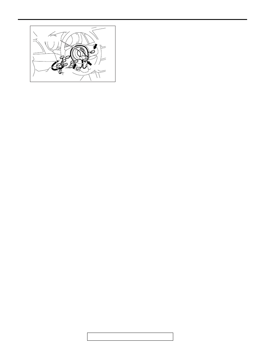
AC709198AB

C-201 (L)

C-202

C-205

Connectors: C-201, C-202, C-205

Clock spring

CRUISE CONTROL

TSB Revision

ENGINE AND EMISSION CONTROL

17-16

STEP 1. Using scan tool MB991958, check the data list 
item 75: Cancel switch, item 86: Main switch, item 91: 
Resume switch and item 92: Set switch.

CAUTION

To prevent damage to scan tool MB991958, always turn the 
ignition switch to the "LOCK" (OFF) position before con-
necting or disconnecting scan tool MB991958.
(1) Connect scan tool MB991958 to the data link connector 

(Refer to 

P.17-10

.)

(2) Turn the ignition switch to the "ON" position.
(3) Set scan tool MB991958 to data reading mode for cruise 

control system (Refer to 

P.17-10

.)

• Item 75: Cancel switch.

• When "CANCEL" switch is pressed, the display on 

scan tool MB991958 should be "ON".

• When "CANCEL" switch is released, the display on 

scan tool MB991958 should be "OFF".

• Item 86: Main switch.

• When "ON/OFF" switch is pressed, the display on 

scan tool MB991958 should be "ON".

• When "ON/OFF" switch is pressed again, the display 

on scan tool MB991958 should be "OFF".

• Item 91: Resume switch.

• When "ACC/RES" switch is pressed, the display on 

scan tool MB991958 should be "ON".

• When "ACC/RES" switch is released, the display on 

scan tool MB991958 should be "OFF".

• Item 92: Set switch.

• When "COAST/SET" switch is pressed, the display 

on scan tool MB991958 should be "ON".

• When "COAST/SET" switch is released, the display 

on scan tool MB991958 should be "OFF".

Q: Is the switch operating properly?

YES : Go to Step 25.
NO :  Go to Step 2.

AC608435

Data link connector

MB991827

MB991824

MB991910

AB

CRUISE CONTROL

TSB Revision

ENGINE AND EMISSION CONTROL

17-17

STEP 2. Measure the power supply voltage at cruise 
control switch connector C-201 by backprobing.
(1) Remove the cruise control switch from the steering wheel 

with the cruise control switch connector connected (Refer to 

P.17-68

.)

(2) Connect the negative (−) battery cable that was 

disconnected when the driver's air bag module was 
removed.

(3) Do not disconnect cruise control switch connector C-201.
(4) Turn the ignition switch to the "ON" position.
(5) Do not operate the cruise control switch.
(6) Measure the power supply voltage between cruise control 

switch connector C-201 terminal number 3 and body 
ground by backprobing.

Q: Is the measured voltage between 4.7 and 5.0 volts?

YES : Go to Step 14.
NO :  Go to Step 3.

AC601563 AD

C-201 Harness connector:
Harness side

CRUISE CONTROL

TSB Revision

ENGINE AND EMISSION CONTROL

17-18

STEP 3. Measure the power supply voltage at ECM 
connector B-10.
(1) Remove the ECM [Refer to GROUP 13A, Engine Control 

Module (ECM) 

P.13A-888

.]

(2) Connect special tool MB992110 between the ECM and the 

body-side harness connector.

(3) Turn the ignition switch to the "ON" position.
(4) Do not operate the cruise control switch.

(5) Measure the power supply voltage between special tool 

48-pin connector terminal number 107 (ECM connector 
B-10 terminal number 107) and body ground.

Q: Is the measured voltage between 4.7 and 5.0 volts?

YES : Go to Step 10.
NO :  Go to Step 4.

STEP 4. Check ECM connector B-10 for loose, corroded or 
damaged terminals, or terminals pushed back in the 
connector.
Refer to GROUP 00E, Harness Connector Inspection 

P.00E-2

.

Q: Is the connector and terminal in good condition?

YES : Go to Step 5.
NO :  Repair or replace the damaged connector. Then go to 

Step 26.

AC709266AB

82 81 80 79 78 77 76 75 74 73 72 71

94 93 92 91 90 89 88 87 86 85 84 83

99 98 97 96 95

100

101

102

103

104

105

106

112

113

114

109 108

107

110

111

115

116

117

118

MB992110

ECM

B-10 (GR)

Special tool 48-pin connector

AC709268AB

Special tool 48-pin connector:
Component side


Content   ..  105  106  107  108   ..