Mitsubishi Lancer Evolution X. Manual - part 105
ENGINE CONTROL
TSB Revision
ENGINE AND EMISSION CONTROL
17-7
SPECIAL TOOL
M1171000600216
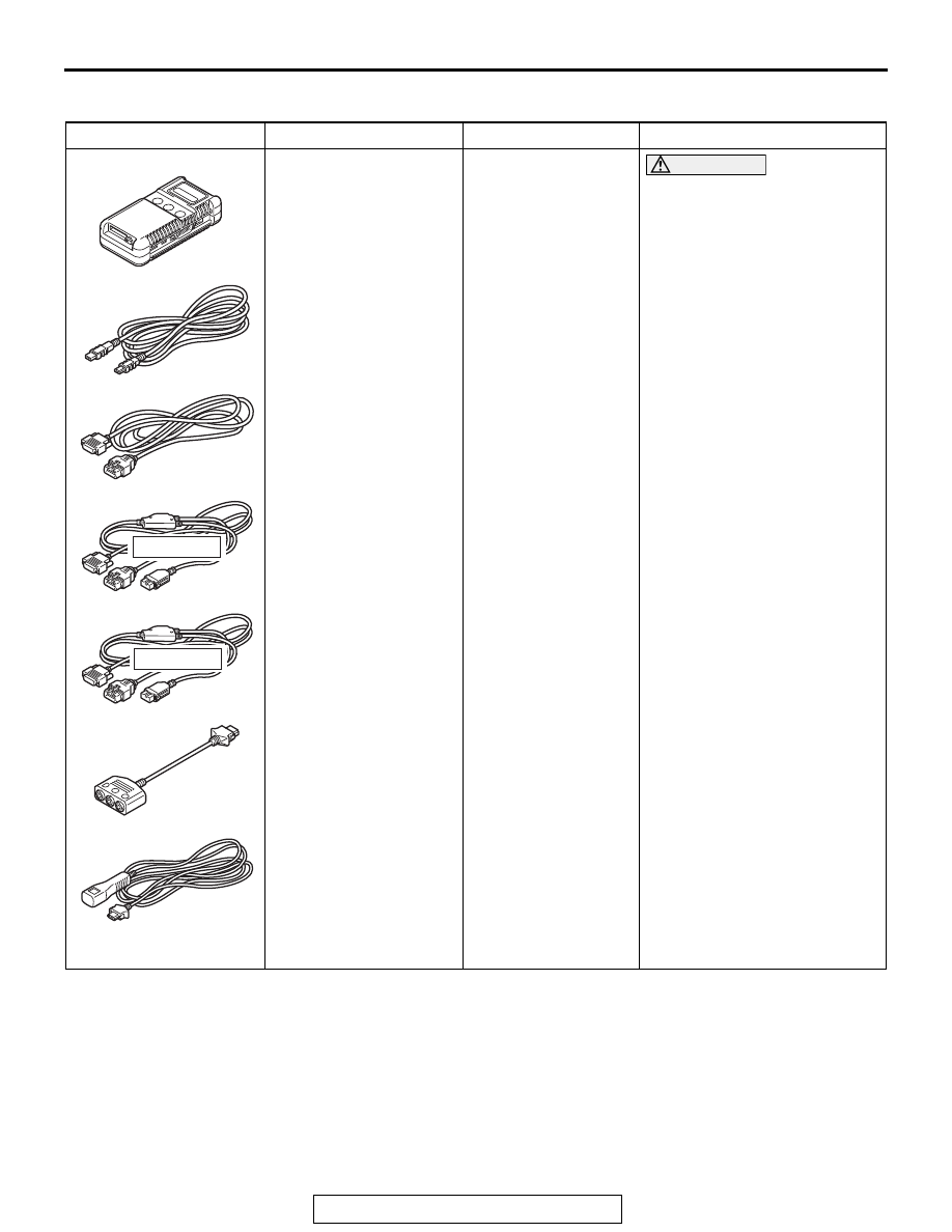
Tool
Tool number and name Supersession
Application
MB991958
a: MB991824
b: MB991827
c: MB991910
d: MB991911
e: MB991914
f: MB991825
g: MB991826
Scan tool (M.U.T.-III sub
assembly)
a: Vehicle
communication
interface (V. C. I.)
b: M.U.T.-III USB cable
c: M.U.T.-III main
harness A (Vehicles
with CAN
communication
system)
d: M.U.T.-III main
harness B (Vehicles
without CAN
communication
system)
e: M.U.T.-III main
harness C (for
Chrysler models only)
f: M.U.T.-III
measurement adapter
g: M.U.T.-III trigger
harness
MB991824-KIT
NOTE: g: MB991826
M.U.T.-III Trigger
Harness is not
necessary when
pushing V.C.I.
ENTER key.
CAUTION
For vehicles with CAN
communication, use
M.U.T.-III main harness A to
send simulated vehicle
speed. If you connect
M.U.T.-III main harness B
instead, the CAN
communication does not
function correctly.
Checking diagnostic trouble
code (DTC)
MB991910
MB991826
MB991958
MB991911
MB991914
MB991824
MB991827
MB991825
Do not use
a
b
c
d
e
f
g
Do not use