Mitsubishi Lancer Evolution X. Manual - part 74


  Index      Mitsubishi     Mitsubishi Lancer Evolution X GS41EVO - service repair manual 2008 year


Search            


Content   ..  72  73  74  75   ..


Mitsubishi Lancer Evolution X. Manual - part 74


OIL PAN

TSB Revision

ENGINE MECHANICAL

11A-49

REMOVAL SERVICE POINTS

.

<<A>> A/C COMPRESSOR AND CLUTCH ASSEM-
BLY REMOVAL

1. Remove the A/C compressor and clutch assembly together 

with the hose from the bracket.

2. Tie the removed A/C compressor and clutch assembly with 

a string at a position where they will not interfere with the 
removal and installation of engine oil pan.

.

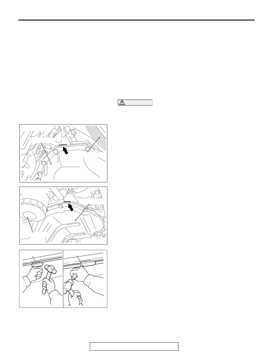
<<B>> ENGINE OIL PAN REMOVAL

1. Remove the engine oil pan mounting bolts.

CAUTION

Do not forcibly drive in special tool MD998727 to avoid 
damage to the engine oil pan seal surface of cylinder block 
assembly.
2. Insert special tool MD998727 from the engine oil pan 

removal groove of the cylinder block assembly. 

3. Lightly tap the special tool with a hammer to slide the oil pan 

seal surface, cut off the liquid gasket, and remove the 
engine oil pan.

AC705459AC

<Engine front>

Engine oil pan

Crankshaft pulley

AC705460 AC

Engine oil pan

<Engine rear>

Engine oil filter

AC102324 AB

MD998727

MD998727

OIL PAN

TSB Revision

ENGINE MECHANICAL

11A-50

INSTALLATION SERVICE POINTS

.

>>A<< ENGINE OIL PAN INSTALLATION

1. Remove all the traces of sealant adhering to the engine oil 

pan and cylinder block assembly using a remover or others. 
Then, degrease them.

2. Apply the sealant without any gap to the mating surface of 

engine oil pan as shown in the figure, and install the engine 
oil pan to the cylinder block assembly.

Specified sealant: Three bond 1217G or equivalent

NOTE: Install the engine oil pan immediately after applying 
sealant.

CAUTION

After the installation, until a sufficient period of time (one 

hour or more) elapses, do not apply the oil or water to the 

sealant application area or start the engine.
3. Tighten the engine oil pan mounting bolts to the specified 

torque.

Tightening torque: 

M6: 10 ± 2 N⋅ m (89 ± 17 in-lb)

M8: 29 ± 2 N⋅ m (22 ± 1 ft-lb)

.

>>B<< ENGINE OIL PAN DRAIN PLUG GASKET 

INSTALLATION

Replace the engine oil pan drain plug gasket with a new one. 
Install the new gasket in the direction shown in the illustration.

.

>>C<< A/C COMPRESSOR AND CLUTCH 

ASSEMBLY INSTALLATION

Tighten A/C compressor and clutch assembly mounting bolts to 
the specified torque in the order of number shown in the illus-
tration.

Tightening torque: 23 ± 6 N⋅ m (17 ± 4 ft-lb)

INSPECTION

M1112002900577

• Check the engine oil pan for cracks.
• Check the engine oil pan sealant-coated surface for dam-

age and deformation.

AC804940AB

φ 2.5 mm 
(

φ 0.1in) 

AC102325AJ

Engine oil 
pan side

Engine oil pan
drain plug gasket

AC506759

AE

1

2

3

A/C compressor 
and clutch assembly

CRANKSHAFT OIL SEAL

TSB Revision

ENGINE MECHANICAL

11A-51

CRANKSHAFT OIL SEAL

REMOVAL AND INSTALLATION

M1112003103476

Required Special Tools:

• MB991883: Flywheel Stopper
• MB991448: Bush Remover And Installer Base

AC902049

1

2

4

2

3

4

5

<M/T>

<TC-SST>

40 N·m
30 ft-lb

N

N

AB

130 N·m
96 ft-lb

to

40 N·m
30 ft-lb

130 N·m
96 ft-lb

to

10 ± 2 N·m
89 ± 17 in-lb

1

5

2

Engine oil

Seating surface: Engine oil
Thread: Three bond 1324 
or exact equivalent

Crankshaft front oil seal removal 
steps 

Crankshaft pulley (Refer to 

P.11A-21

)

>>

C

<<

1.

Crankshaft front oil seal

Crankshaft rear oil seal removal 
steps 

Transaxle assembly (Refer to 
GROUP 22A, Transaxle Assembly 

P.22A-128

<M/T>), (Refer to 

GROUP 22C, Transaxle Assembly 

P.22C-412

<TC-SST>)

<<

A

>>

>>

B

<<

2.

Flywheel bolts

>>

B

<<

3.

Flywheel hub <TC-SST>

>>

B

<<

4.

Flywheel

>>

A

<<

5.

Crankshaft rear oil seal case 
assembly

CRANKSHAFT OIL SEAL

TSB Revision

ENGINE MECHANICAL

11A-52

REMOVAL SERVICE POINT

.

<<A>> FLYWHEEL BOLTS REMOVAL

Fix the flywheel using special tool MB991883, and loosen the 
flywheel bolts.

INSTALLATION SERVICE POINTS

.

>>A<< CRANKSHAFT REAR OIL SEAL CASE 
ASSEMBLY INSTALLATION

1. Remove all the traces of sealant adhering to the cylinder 

block and ladder frame using a remover or others. Then, 
degrease them using.

2. Apply the sealant without any gap to the cylinder block and 

ladder frame as shown in the figure, and install the 
crankshaft rear oil seal case assembly.

Specified sealant: Three bond 1227D or equivalent

NOTE: Install the crankshaft rear oil seal case assembly 
immediately after applying sealant.

3. Apply a small amount of engine oil to the entire inner 

diameter of the oil seal lip, and install the crankshaft rear oil 
seal case assembly.

CAUTION

After the installation, until a sufficient period of time (one 
hour or more) elapses, do not apply the oil or water to the 
sealant application area or start the engine.
4. Tighten the crankshaft rear oil seal case assembly mounting 

bolts to the specified torque.

Tightening torque: 10 ± 2 N⋅ m (89 ± 17 in-lb)

.

>>B<< FLYWHEEL/FLYWHEEL HUB 
<TC-SST>/FLYWHEEL BOLTS INSTALLATION

1. Remove the engine oil and deposits from the flywheel bolt 

threads, crankshaft tapped hole, and flywheel.

2. Install the flywheel and flywheel hub <TC-SST> to the 

crankshaft.

AC506761 AD

MB991883

Cylinder block

AC704960AC

Cylinder block

Ladder frame

φ 2 mm or φ 3 mm
(

φ 0.08 in or φ 0.12 in)

1mm (0.04in)


Content   ..  72  73  74  75   ..