Mitsubishi Lancer Evolution X. Manual - part 73


  Index      Mitsubishi     Mitsubishi Lancer Evolution X GS41EVO - service repair manual 2008 year


Search            


Content   ..  71  72  73  74   ..


Mitsubishi Lancer Evolution X. Manual - part 73


VALVE STEM SEAL

TSB Revision

ENGINE MECHANICAL

11A-45

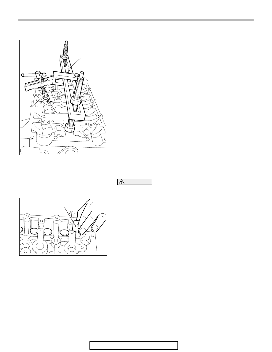
>>C<< VALVE SPRING RETAINER LOCK 
INSTALLATION

In the same manner as removal, use special tool MD998772 
with special tool MB992090 and special tool MB992089 
attached to compress the valve spring, and install the valve 
spring retainer lock.

.

>>D<< VALVE TAPPET INSTALLATION

1. Apply a small amount of engine oil to the valve tappets.

CAUTION

Be sure to install the valve tappets in the same position as 
before.
2. Install the valve tappet to the cylinder head.

.

AC509271

AC

MD998772

MB992090

MB992089

AC509270

AC

Valve tappet

VALVE STEM SEAL

TSB Revision

ENGINE MECHANICAL

11A-46

>>E<< THRUST CAMSHAFT BEARING 
CAP/CAMSHAFT BEARING CAP/OIL FEEDING 
CAMSHAFT BEARING CAP INSTALLATION

1. Install the camshaft bearing caps to the cylinder heads.

NOTE: Because the thrust camshaft bearing cap and cam-
shaft bearing cap are the same in shape, check the cap 
number and additionally its symbol to identify the intake and 
exhaust sides for correct installation.

2. Tighten each camshaft bearing cap to the specified torque in 

the order of number shown in the figure in two or three 
steps.

Tightening torque: 12 ± 1 N⋅ m (107 ± 8 in-lb)

.

AC506778

AC

8

8

7

7

6

6

5

5

4

4

3

3

2

2

1

1

E  5

Engine front

Camshaft bearing cap

Camshaft bearing cap

Bearing cap No.

Identification of intake side 
and exhaust side

VALVE STEM SEAL

TSB Revision

ENGINE MECHANICAL

11A-47

>>F<< CAMSHAFT BEARING/CAMSHAFT AND 
CAMSHAFT SPROCKET ASSEMBLY (EXHAUST 
SIDE) INSTALLATION

CAUTION

• Be careful not to drop the camshaft bearing.
• When installing the camshaft and camshaft sprocket 

assembly (exhaust side), be careful not to let the cam-
shaft bearing which is installed to the front cam bearing 
deviate from its position.

When replacing the camshaft bearing, according to the identifi-
cation mark of front camshaft bearing cap in the table below, 
select a camshaft bearing with the corresponding size. Note 
that the identification mark of camshaft bearing is stamped on 
the place shown in the figure.

.

>>G<< FRONT CAMSHAFT BEARING CAP 
ASSEMBLY INSTALLATION

CAUTION

When the mounting bolts are tightened with the front cam-
shaft bearing cap tilted, the front camshaft bearing cap is 
damaged. Install the front camshaft bearing cap properly 
to the cylinder head and camshaft.
1. Install the front camshaft bearing cap to the cylinder head, 

and temporarily tighten the front camshaft bearing cap to the 
specified torque in the order of the figure (1).

Tightening torque: 17 ± 3 N⋅ m (13 ± 2 ft-lb)

2. Tighten the front camshaft bearing cap again to the specified 

torque in the order of the figure (2).

Tightening torque: 30 ± 2 N⋅ m (23 ± 1 ft-lb)

Front camshaft bearing cap

Camshaft bearing 
identification mark

Identification 
mark

Journal diameter 
mm (in)

1

40.000 - 40.008 
(1.5748 - 1.5751)

1

2

40.008 - 40.016 
(1.5751 - 1.5754)

2

3

40.016 - 40.024 
(1.5754 - 1.5757)

3

AC611697

AD

Front camshaft 
bearing cap

Identification
mark

AC708893

Notch

Identification mark

Oil hole

AD

AC511062

AC

4

3

2

1

4

3

2

1

(1)

(2)

Engine front

Front 
camshaft
bearing
cap
assembly

OIL PAN

TSB Revision

ENGINE MECHANICAL

11A-48

OIL PAN

REMOVAL AND INSTALLATION

M1112002802811

Required Special Tool:

• MD998727: Oil Pan FIPG Cutter

Pre-removal operation
• Engine Room Under Cover Front A, B, Engine Room 

Under Cover Center and Engine Room Side Cover (RH) 

Removal (Refer to GROUP 51, Under Cover 

P.51-15

).

• Engine Oil Draining (Refer to GROUP 12, On-vehicle Ser-

vice − Engine Oil Replacemen

P.12-4

).

• Drive Belt Removal (Refer to 

P.11A-21

).

Post-installation operation
• Drive Belt Installation (Refer to 

P.11A-21

).

• Engine Oil Refilling (Refer to GROUP 12, On-vehicle Ser-

vice − Engine Oil Replacement 

P.12-4

).

• Engine Room Under Cover Front A, B, Engine Room 

Under Cover Center and Engine Room Side Cover (RH) 

Installation (Refer to GROUP 51, Under Cover 

P.51-15

).

AC708918

4

3

5

1

2

39 ± 5 N·m
29 ± 3 ft-lb

10 ± 2 N·m
89 ± 17 in-lb

29 ± 2 N·m
22 ± 1 ft-lb

23 ± 6 N·m
17 ± 4 ft-lb

23 ± 6 N·m
17 ± 4 ft-lb

N

AB

6

29 ± 2 N·m
22 ± 1 ft-lb

Removal steps 

1.

A/C compressor assembly 
connector connection

<<

A

>>

>>

C

<<

2.

A/C compressor and clutch 
assembly

3.

A/C compressor bracket

4.

Engine oil pan drain plug

>>

B

<<

5.

Engine oil pan drain plug gasket

<<

B

>>

>>

A

<<

6.

Engine oil pan

Removal steps (Continued)


Content   ..  71  72  73  74   ..