Mitsubishi Lancer Evolution X. Manual - part 67
CRANKSHAFT PULLEY
TSB Revision
ENGINE MECHANICAL
11A-21
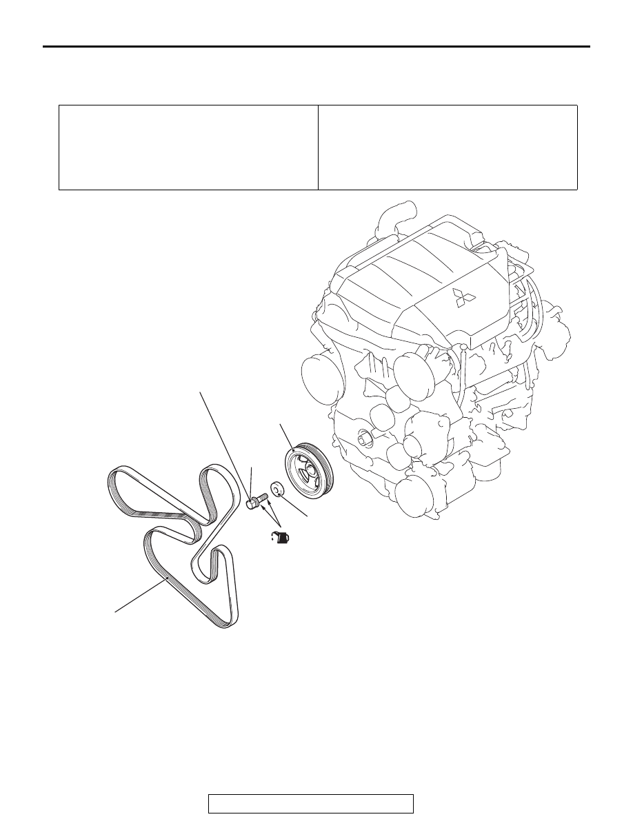
CRANKSHAFT PULLEY
REMOVAL AND INSTALLATION
M1112001603226
Pre-removal operation
• Engine Room Under Cover Front A, B, Engine Room
Under Cover Center and Engine Room Side Cover (RH)
Removal (Refer to GROUP 51, Under Cover
• Radiator Condenser Tank Bracket Removal (Refer to
GROUP 14, Radiator
).
Post-installation operation
• Drive Belt Tension Check (Refer to
• Radiator Condenser Tank Bracket Installation (Refer to
).
• Engine Room Under Cover Front A, B, Engine Room
Under Cover Center and Engine Room Side Cover (RH)
Installation (Refer to GROUP 51, Under Cover
AC704354AC
1
2
3
4
to 0 N·m to
250 N·m
184 ft-lb
to +60˚
110 N·m
81 ft-lb
(Engine oil)
Removal steps
<<
A
>>
>>
B
<<
1.
Drive belt
<<
B
>>
>>
A
<<
2.
Crankshaft pulley center bolt
<<
B
>>
>>
A
<<
3.
Crankshaft pulley washer
•
Engine mounting bracket (Refer
to GROUP 32, Engine Mounting
)
>>
A
4.
Crankshaft pulley
Removal steps (Continued)