Mitsubishi Lancer Evolution X. Manual - part 65
ON-VEHICLE SERVICE
TSB Revision
ENGINE MECHANICAL
11A-13
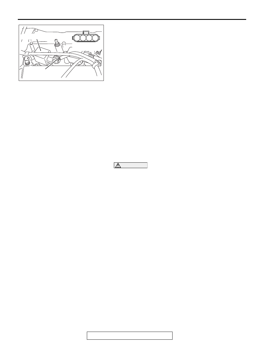
3. Set the timing light to the power supply line (terminal No. 4)
of the ignition coil No. 1.
4. Start the engine.
5. Run the engine at idle for 2 minutes.
6. Check the actual ignition timing is at the standard value.
Standard value: Approximately 10° BTDC
NOTE: Ignition timing fluctuates about
±
7
°
, even under nor-
mal operating condition.
NOTE: It is automatically further advanced by about 5
°
from
10
°
Before Top Dead Center at higher altitudes.
NOTE: Wait till approximately 1 minute passes after the
engine started, and check the ignition timing when the
engine stabilized.
7. Check the idle speed. Select item number 2 and take a
reading of the idle speed.
Curb idle speed: 700 ± 100 r/min
NOTE: The idle speed is controlled automatically by the idle
air control system.
8. If the idle speed is outside the standard value, refer to
GROUP 13A, Multiport Fuel Injection (MFI) − Multiport Fuel
Injection (MFI) Diagnosis − Symptom Chart
.
9. Remove the timing light.
CAUTION
To prevent damage to scan tool MB991958, always turn the
ignition switch to the "LOCK" (OFF) position before con-
necting or disconnecting scan tool MB991958.
10.Disconnect scan tool MB991958 from the data link
connector.
IDLE MIXTURE CHECK
M1111002101872
Required Special Tool:
MB991958: Scan Tool (M.U.T.-III Sub Assembly)
• MB991824: V.C.I.
• MB991827: M.U.T.-III USB Cable
• MB991910: M.U.T.-III Main Harness A
1. Before inspection, set the vehicle in the following condition:
• Engine coolant temperature: 80 − 95° C (176 − 203° F)
• Lights and all accessories: OFF
• Transaxle: Neutral (P range on vehicles with TC-SST)
NOTE: On vehicles for Canada, the headlight, taillight, etc.
remain lit even when the lighting switch is in "OFF" position
but this is no problem for checks.
AK703277
M
1
2
3
4
AD
Power supply line
(terminal No. 4)
Equipment side
connector
No. 1 ignition coil