Mitsubishi Lancer Evolution X. Manual - part 38


  Index      Mitsubishi     Mitsubishi Lancer Evolution X GS41EVO - service repair manual 2008 year


Search            


Content   ..  36  37  38  39   ..


Mitsubishi Lancer Evolution X. Manual - part 38


DIAGNOSIS

TSB Revision

CONTROLLER AREA NETWORK (CAN)

54C-177

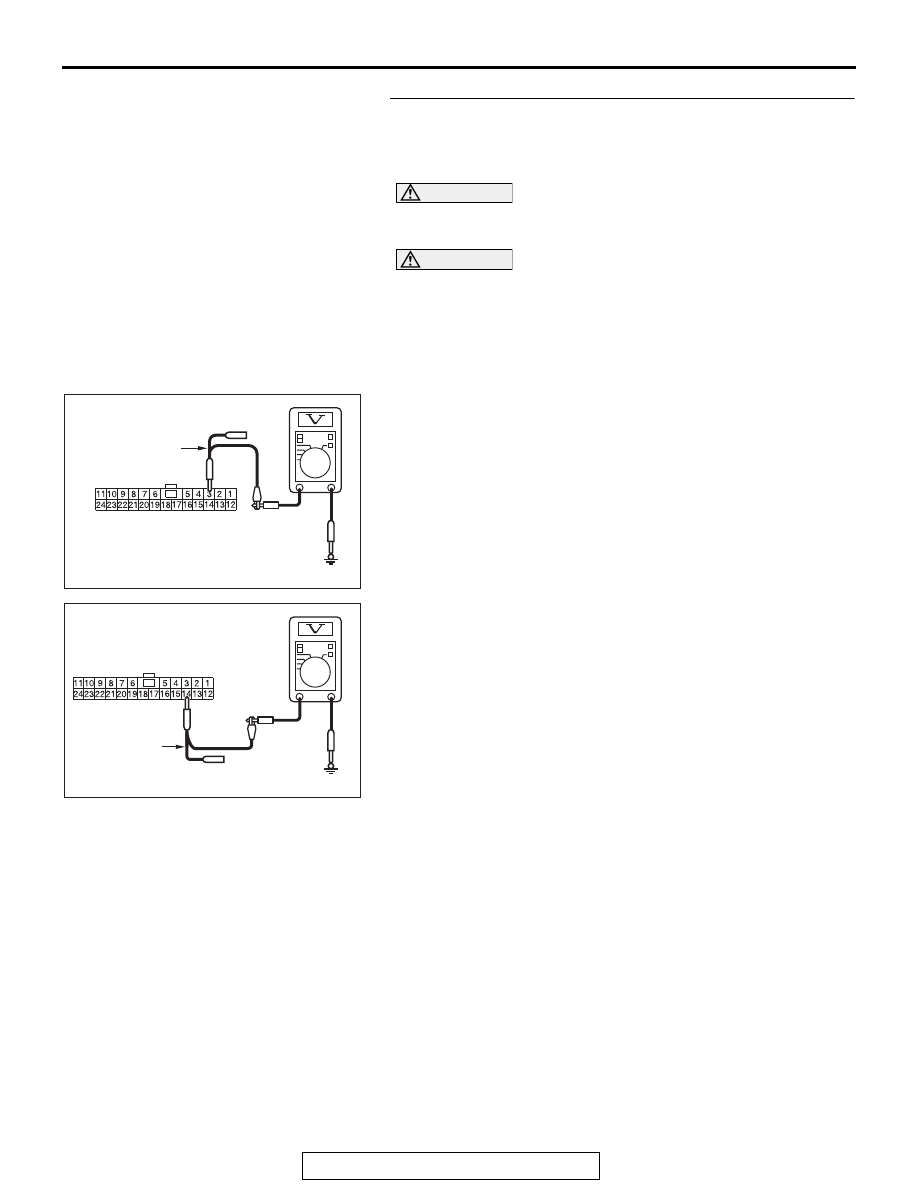
STEP 13. Check the wiring harness between joint 
connector (CAN1) C-105 and combination meter connector 
C-04 for a short to power supply. Measure the voltage at 
joint connector (CAN1) C-105.

CAUTION

A digital multimeter should be used. For details refer to 

P.54C-7

.

CAUTION

The test wiring harness should be used. For details refer to 

P.54C-7

.

(1) Disconnect joint connector (CAN1), and measure the 

voltage at the wiring harness side of joint connector 
(CAN1).

(2) Turn the ignition switch to the ON position.
(3) Measure the voltage between joint connector (CAN1) 

terminal 3 and body ground.

OK: 4.7 V or less

(4) Measure the voltage between joint connector (CAN1) 

terminal 14 and body ground.

OK: 4.7 V or less

Q: Do all the voltages measure 4.7 V or less?

YES (vehicles with KOS) : Go to Step 14.
YES (vehicles with WCM) : Go to Step 15.
NO (vehicles with KOS and WCM) : Go to Step 24.

AC608178

TEST 
HARNESS

Harness side: C-105

BH

AC608178

Harness side: C-105

BI

TEST 
HARNESS

DIAGNOSIS

TSB Revision

CONTROLLER AREA NETWORK (CAN)

54C-178

STEP 14. Check the wiring harness between joint 
connector (CAN1) C-105 and KOS-ECU connector C-05 for 
a short to power supply. Measure the voltage at joint 
connector (CAN1) C-105.

CAUTION

A digital multimeter should be used. For details refer to 

P.54C-7

.

CAUTION

The test wiring harness should be used. For details refer to 

P.54C-7

.

(1) Disconnect joint connector (CAN1), and measure the 

voltage at the wiring harness side of joint connector 
(CAN1).

(2) Turn the ignition switch to the ON position.
(3) Measure the voltage between joint connector (CAN1) 

terminal 9 and body ground.

OK: 4.7 V or less

(4) Measure the voltage between joint connector (CAN1) 

terminal 22 and body ground.

OK: 4.7 V or less

Q: Do all the voltages measure 4.7 V or less?

YES : Go to Step 16.
NO :  Go to Step 25.

AC608178

TEST 
HARNESS

Harness side: C-105

BJ

AC608178

Harness side: C-105

BK

TEST 
HARNESS

DIAGNOSIS

TSB Revision

CONTROLLER AREA NETWORK (CAN)

54C-179

STEP 15. Check the wiring harness between joint 
connector (CAN1) C-105 and WCM connector C-07 for a 
short to power supply. Measure the voltage at joint 
connector (CAN1) C-105.

CAUTION

A digital multimeter should be used. For details refer to 

P.54C-7

.

CAUTION

The test wiring harness should be used. For details refer to 

P.54C-7

.

(1) Disconnect joint connector (CAN1), and measure the 

voltage at the wiring harness side of joint connector 
(CAN1).

(2) Turn the ignition switch to the ON position.
(3) Measure the voltage between joint connector (CAN1) 

terminal 7 and body ground.

OK: 4.7 V or less

(4) Measure the voltage between joint connector (CAN1) 

terminal 20 and body ground.

OK: 4.7 V or less

Q: Do all the voltages measure 4.7 V or less?

YES : Go to Step 16.
NO :  Go to Step 26.

AC608178

TEST 
HARNESS

Harness side: C-105

BL

AC608178

Harness side: C-105

BM

TEST 
HARNESS

DIAGNOSIS

TSB Revision

CONTROLLER AREA NETWORK (CAN)

54C-180

STEP 16. Check the wiring harness between joint 
connector (CAN1) C-105 and SRS-ECU connector C-37 for 
a short to power supply. Measure the voltage at joint 
connector (CAN1) C-105.

CAUTION

A digital multimeter should be used. For details refer to 

P.54C-7

.

CAUTION

The test wiring harness should be used. For details refer to 

P.54C-7

.

(1) Disconnect joint connector (CAN1), and measure the 

voltage at the wiring harness side of joint connector 
(CAN1).

(2) Turn the ignition switch to the ON position.
(3) Measure the voltage between joint connector (CAN1) 

terminal 8 and body ground.

OK: 4.7 V or less

(4) Measure the voltage between joint connector (CAN1) 

terminal 21 and body ground.

OK: 4.7 V or less

Q: Do all the voltages measure 4.7 V or less?

YES : Go to Step 17.
NO :  Go to Step 27.

AC608178

TEST 
HARNESS

Harness side: C-105

BN

AC608178

Harness side: C-105

BO

TEST 
HARNESS


Content   ..  36  37  38  39   ..