Mitsubishi Lancer Evolution X. Manual - part 39
DIAGNOSIS
TSB Revision
CONTROLLER AREA NETWORK (CAN)
54C-181
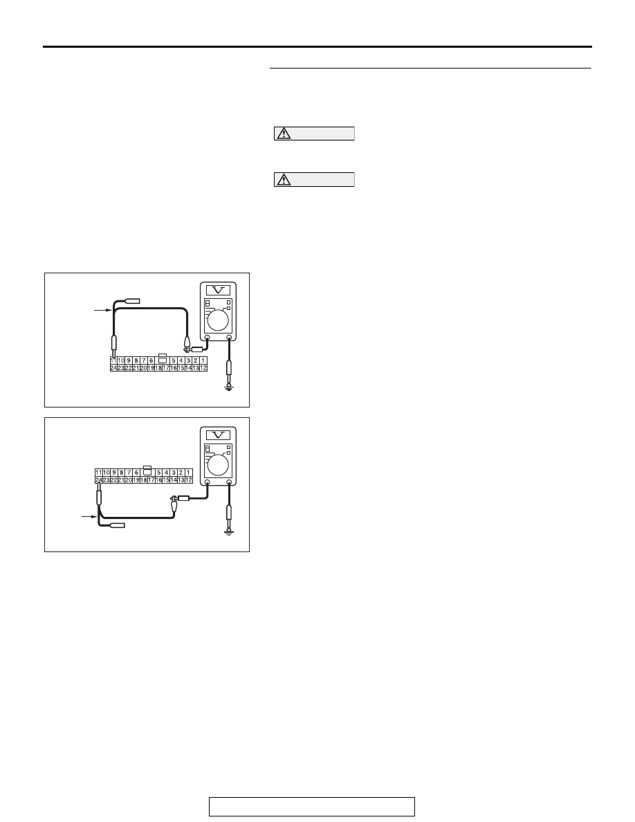
STEP 17. Check the wiring harness between joint
connector (CAN1) C-105 and occupant classification-ECU
connector D-39-2 for a short to power supply. Measure the
voltage at joint connector (CAN1) C-105.
CAUTION
A digital multimeter should be used. For details refer to
CAUTION
The test wiring harness should be used. For details refer to
(1) Disconnect joint connector (CAN1), and measure the
voltage at the wiring harness side of joint connector
(CAN1).
(2) Turn the ignition switch to the ON position.
(3) Measure the voltage between joint connector (CAN1)
terminal 11 and body ground.
OK: 4.7 V or less
(4) Measure the voltage between joint connector (CAN1)
terminal 24 and body ground.
OK: 4.7 V or less
Q: Do all the voltages measure 4.7 V or less?
YES (vehicles without hands free system) : Go to Step
19.
YES (vehicles with hands free system) : Go to Step 18.
NO : Go to Step 28.
AC608178
TEST
HARNESS
Harness side: C-105
BP
AC608178
Harness side: C-105
BQ
TEST
HARNESS