Mitsubishi Lancer Evolution IX. Manual - part 241


  Index      Mitsubishi     Mitsubishi Lancer Evolution IX - service repair manual


Search            


Content   ..  239  240  241  242   ..


Mitsubishi Lancer Evolution IX. Manual - part 241


SYMPTOM PROCEDURES

SMART WIRING SYSTEM (SWS) USING SWS MONITOR

54C-223

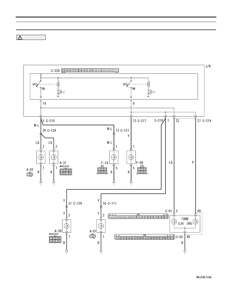
INSPECTION PROCEDURE I-3: Any of the turn-signal lamps does not illuminate. <RH drive vehicles>

CAUTION

Whenever the ECU is replaced, ensure that the 
input and output signal circuits are normal.

SIDE
TURN
SIGNAL
LAMP
(LH)

TURN-SIGNAL
LAMP RELAY: LH

(                                     )

HEADLAMP
ASSEMBLY
(LH)

REAR
COMBINATION
LAMP (RH)

REAR
COMBINATION
LAMP (LH)

HEADLAMP
ASSEMBLY
(RH)

SIDE TURN
SIGNAL LAMP
(RH)

COMBINATION
METER

J/B SIDE

ETACS-ECU

(                                     )

TURN-SIGNAL
LAMP RELAY: RH

Wire colour code
B : Black     LG : Light green     G : Green     L : Blue     W : White     Y : Yellow     SB : Sky blue
BR : Brown     O : Orange     GR : Gray     R : Red     P : Pink     V : Violet

Turn-Signal Lamps Circuit <RHD>

SYMPTOM PROCEDURES

SMART WIRING SYSTEM (SWS) USING SWS MONITOR

54C-224

COMMENTS ON TROUBLE SYMPTOM

If any of the turn-signal lamps does not illuminate 
normally, wiring harness connector(s) or the bulb 
may be defective.

POSSIBLE CAUSES

• Defective turn-signal lamp bulb

• Damaged harness wires and connectors

DIAGNOSTIC PROCEDURE

Step 1. Connector check: A-39 <front RH> or 
A-31 <front LH> headlamp assembly connector, 
A-01 <side RH> or A-02 <side LH> side 
turn-signal lamp connector, F-08 <rear RH> or 
F-14 <rear LH> rear combination lamp connector, 
C-02 <turn-signal indicator lamp> and C-01 
<turn-signal indicator lamp (LH)> combination 
meter connector

AC310434

Connectors: A-01, A-39
<RHD>

A-39

A-01 (GR)

Harness side

A-01

Harness side

A-39

AB

AC310476

Connectors: A-02, A-31
<RHD>

A-31

A-02 (GR)

Harness side

A-02

Harness side

A-31

AB

AC310470

Connectors: F-08, F-14
<RHD>

F-14

F-08

Harness side

F-08

Harness side

F-14

AC

SYMPTOM PROCEDURES

SMART WIRING SYSTEM (SWS) USING SWS MONITOR

54C-225

Q: Is the check result normal?

YES : 

Go to Step 2.

NO : 

Repair the defective connector.

Step 2. Check the bulb(s) of the turn-signal lamps 
or the turn-signal indicator lamps.
Check the bulb(s) of the defective lamp.

Q: Is the check result normal?

YES : 

Go to Step 3.

NO : 

Replace the bulb(s) of the defective lamp.

AC310457

Connectors: C-01, C-02

AB

<RHD>

C-01
Harness side

C-02 
Harness side

31

32

33

34

35

36

37

38

39

40

41

42

43

44

45

46

47

48

49

50

51

C-01

C-02(L)

SYMPTOM PROCEDURES

SMART WIRING SYSTEM (SWS) USING SWS MONITOR

54C-226

Step 3. Resistance measurement at the A-39 
<front RH> or A-31 <front LH> headlamp 
assembly connector, the A-01 <side RH> or A-02 
<side LH> side turn-signal lamp connector, the 
F-08 <rear RH> or F-14 <rear LH> rear 
combination lamp connector, the C-02 
<turn-signal indicator lamp> combination meter 
connector

(1) Disconnect the connector, and measure at the 

wiring harness side.

AC310434

Connectors: A-01, A-39
<RHD>

A-39

A-01 (GR)

Harness side

A-01

Harness side

A-39

AB

AC310476

Connectors: A-02, A-31
<RHD>

A-31

A-02 (GR)

Harness side

A-02

Harness side

A-31

AB

AC310470

Connectors: F-08, F-14
<RHD>

F-14

F-08

Harness side

F-08

Harness side

F-14

AC

AC310456

Connector: C-02
<RHD>

AK

Harness side

31

35

36

37

38

39

40

41

45

46

47

48

49

50

51

34

44

33

43

32

42

C-02 (L)


Content   ..  239  240  241  242   ..