Mitsubishi Lancer Evolution 8. Manual - part 153
FUEL SUPPLY – FUEL TANK
13B-2
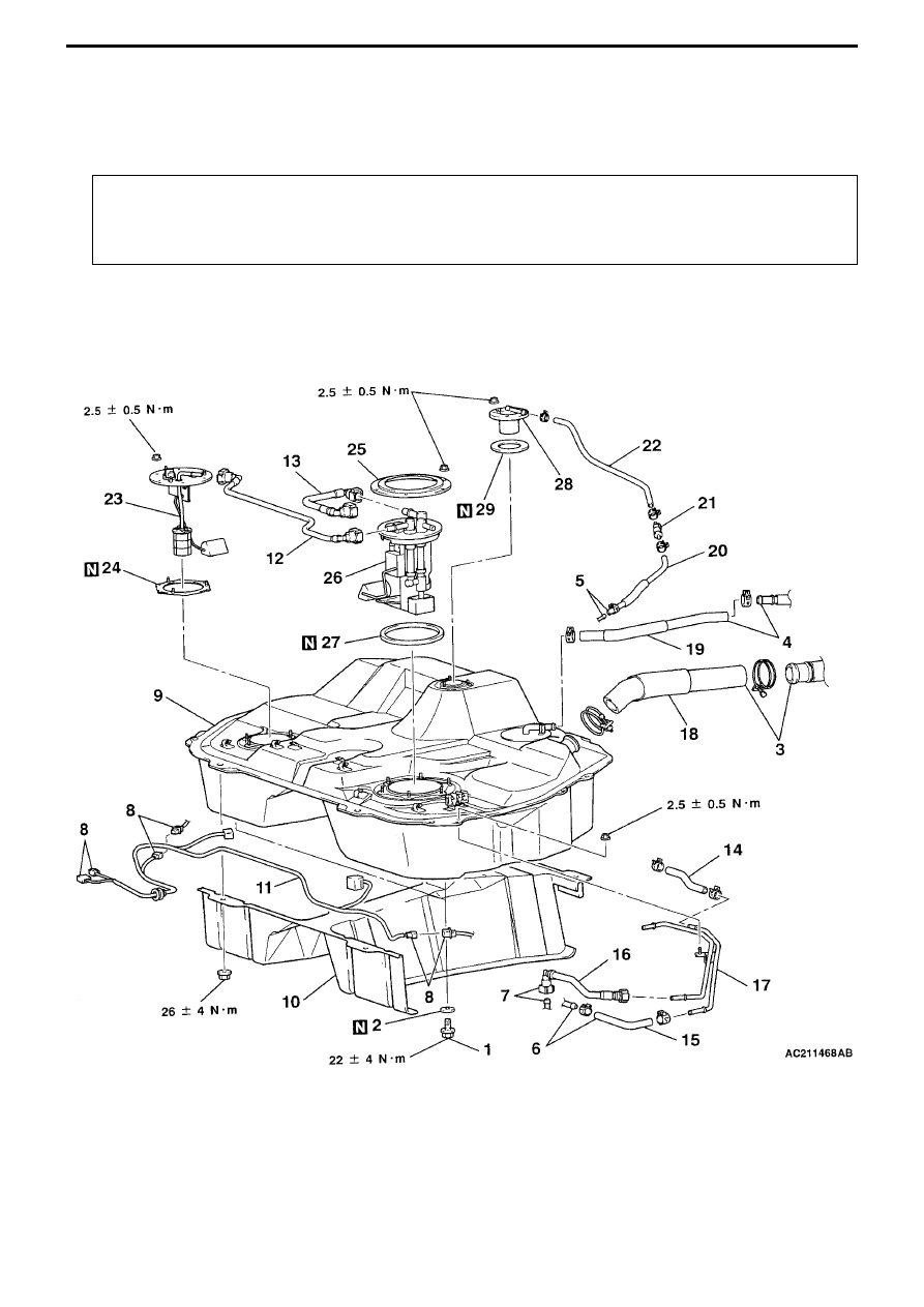
Fuel Tank
Disassembly and Assembly
Work that needs to be done before disassembly and
after assembly
• Measures to prevent fuel escaping (only prior to removal)
• Emptying or filling of fuel
• Checking for any fuel leaks (only after assembly)
• Removal and fitting of propeller shaft
• Removal and fitting of centre exhaust pipe
<Fuel tank ASSY>