Mitsubishi Lancer Evolution 8. Manual - part 130
SWS – TROUBLESHOOTING
54B-43
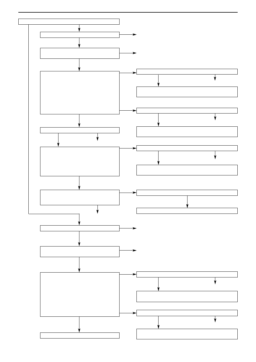
From previous page
Check connectors C-210, D-03
Check the harness between the electric window sub
switch (rear: RH) and the junction box, and repair
Check connector D-03
Check the harness between the electric window sub
switch (rear: RH) and the body earth, and repair
Check connector D-03
Check the harness between the electric window motor
(rear: RH) and the body earth, and repair
Confirm the trouble symptoms
Replace the electric window module assembly (rear :RH)
Check connectors C-210, D-03
Check the harness between the electric window sub
switch (rear: LH) and the junction box, and repair
Check connector D-13
Check the harness between the electric window sub
switch (rear: LH) and the body earth, and repair
Check connector E-102
Check the electric window sub switch (rear :
RH) (see Chap. 42 Doors *)
Check connector E-101
Check connector E-105
Check the electric window sub switch (rear :
LH) (see Chap. 42 Doors *)
To Next page
Measure at Electric window sub switch
(rear : LH) connector E-105
• Detach the connector and measure at the
harness side
• Ignition switch : ON
(1) Connectivity between 4 & body earth
OK: Battery voltage
(2) Connectivity between 1 & body earth
OK: Connectivity
Measure at Electric window motor
(rear : RH) connector E-101
• Detach the connector and measure at the
harness side
• Connectivity between 5 & body earth
OK: Connectivity
Check the harness between the electric
window motor (rear : RH) and the power
widow sub-switch (rear : RH)
Measure at Electric window sub switch
(rear : RH) connector E-102
• Detach the connector and measure at the
harness side
• Ignition switch : ON
(1) Connectivity between 4 & body earth
OK: Battery voltage
(2) Connectivity between 1 & body earth
OK: Connectivity
Note * : See ’00-5 Lancer Cedia Servicing Manual (No. 1036K00)
NG (2)
Repair
Replace
Repair
NG (3)
OK
NG (2)
NG
NG
NG (1)
OK
OK
OK
OK
OK
OK
OK
OK
OK
OK
NG
NG
NG
NG
NG
NG
NG
NG
NG
NG
OK
OK
NG
NG (2)
NG (1)
NG
Repair
Repair
Repair
Repair
Repair
Repair
Repair
Replace