Mitsubishi Lancer Evolution 8. Manual - part 131


  Index      Mitsubishi     Mitsubishi Lancer Evolution 8 - service repair manual


Search            


Content   ..  129  130  131  132   ..


Mitsubishi Lancer Evolution 8. Manual - part 131


SWS – TROUBLESHOOTING

54B-47

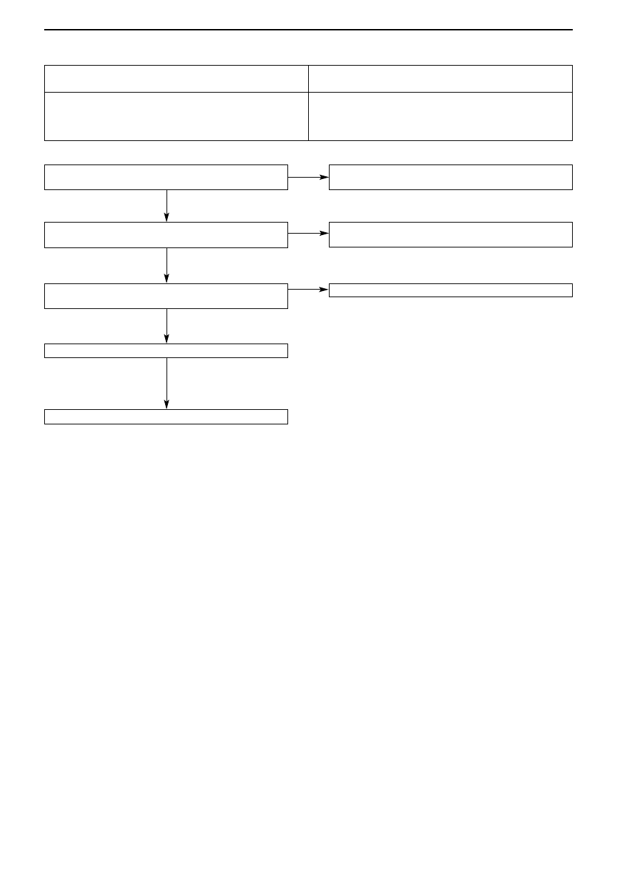
Is the electric window trapping prevention function
working properly? (See Chap.42 Doors*)

Check the electric window operating current (See
Chap.42 Doors*)

Is the door window glass installed correctly? (See
Chap.42 Doors*)

Confirm the trouble symptoms 

Replace the electric window motor assembly

To Inspection procedure D-7 Electric window trapping
prevention function not working correctly  (p.54B-48)

Adjust and replace the door window fault.
(See Chap.42 Doors*)

Adjust the door window glass. (See Chap.42 Doors*)

Inspection procedure D-6

Note:

See ’00-5 Lancer Cedia Servicing Manual (No. 1036K00)

While the window is winding up, it automatically starts to
come down again

Probable Cause

If there is a large resistance to the movement of the window
glass when the electric window is being raised, then it is
judged that the window is trapping an object and it is lowered
by approx. 150 mm.

• Error in adjustment of window glass
• Fault or deformation in glass sliding mechanism
• Fault in electric window motor assembly
• Fault in window regulator assembly

OK

OK

OK

NG

NG

NG

NG

SWS – TROUBLESHOOTING

54B-48

Inspection procedure D-7

Check the electric window operating current (See
Chap.42  Doors *)

Adjust and replace door window fault (See Chap. 42
Doors *)

Check connectors E-02, E-04

Check connector C-33

Check the harness between the electric window main
switch (front: LH) and the body earth, and repair

Check the harness between the electric window sub
switch (front: LH) and electric window motor (front: LH),
and repair

Confirm the trouble symptoms 

Replace the electric window motor assembly (front: LH)

Measure at Electric window main switch connector E-02
and Electric window motor (front: RH) connector E-04
• Detach the connector and measure at the harness side
• Connectivity between the following terminals
OK: Connectivity
Electric window

Electric window

main switch

motor (front RH)

8

5

9

2

10

3

12

6

Does the trapping prevention function work on any of the
respective electric windows?
NG:  (1) Front: RH electric window: Not working

(2) Front: LH electric window: Not working
(3) Rear: RH electric window: Not working
(4) Rear: LH electric window: Not working

Check the harness between the electric
window main switch and the electric window
motor (front: RH)

Confirm the trouble symptoms 

Replace the electric window motor assembly
(front: RH)

Check connector E-09

Measure at the Electric window motor (front:
LH) connector E-09
• Detach the connector and measure at the

harness side

• Connectivity between 5 and body earth
OK: Connectivity

Check connector E-06

To next page

Measure at Electric window sub switch
(front: LH) connector E-06 and Electric
window motor (front: LH) connector E-09
• Detach the connector and measure at the

harness side

• Connectivity between the following

terminals

OK: Connectivity
Electric window

Electric window

sub switch (front: LH)

motor (front LH)

3

6

8

3

2

2

Note: See ’00-5 Lancer Cedia Servicing Manual (No. 1036K00)

Electric window trapping prevention function not working correctly

Probable Cause

There is probably a fault in the rotation detector sensor in the electric window motor • Fault in electric window motor assembly

OK

NG (4)

OK

NG

NG

OK

OK

OK

OK

OK

NG

NG

NG

NG

OK

NG

Repair

Repair

OK

NG

OK

NG

Repair

NG (1)

NG

NG

NG

Repair

Repair

Repair

NG (3)

NG (2)

SWS – TROUBLESHOOTING

54B-49

From previous page

Check connector E-101

Measure at the Electric window motor (rear:
RH) connector E-101
• Detach the connector and measure at the

harness side

• Connectivity between 5 and body earth
OK: Connectivity

Check connector E-102

Check connector E-104

Measure at the Electric window motor (rear
LH) connector E-104
• Detach the connector and measure at the

harness side

• Connectivity between 5 and body earth
OK: Connectivity

Check connectors E-105

Measure at Electric window sub switch
(rear: RH) E-102 and Electric window motor
(rear: LH) connector E-104
• Detach the connector and measure at the

harness side

• Connectivity between the following

terminals

OK: Connectivity
Electric window

Electric window

sub switch (rear: LH)

motor (rear: LH)

3

6

8

3

2

2

Measure at Electric window sub switch
(rear: RH) E-102 and Electric window motor
(rear: RH) connector E-101
• Detach the connector and measure at the

harness side

• Connectivity between the following

terminals

OK: Connectivity
Electric window

Electric window

sub switch (rear: RH)

motor (rear: RH)

3

6

8

3

2

2

Check connector D-03

Check the harness between the electric window main
switch (rear: RH) and the body earth, and repair

Check the harness between the electric window sub
switch (rear: RH) and electric window motor (front: RH),
and repair

Confirm the trouble symptoms 

Replace the electric window motor assembly (rear: RH)

Check connector D-13

Check the harness between the electric window main
switch (rear: LH) and the body earth, and repair

Check the harness between the electric window sub
switch (rear: LH) and electric window motor (rear: LH),
and repair

Confirm the trouble symptoms 

Replace the electric window motor assembly (rear: LH)

NG (4)

NG 

OK

OK

OK

OK

OK

OK

OK

NG

OK

OK

OK

OK

NG

NG

OK

NG

NG

NG

NG

NG

NG

NG

NG

NG

NG

NG (3)

Repair

Repair

Repair

Repair

Repair

Repair

Repair

Repair

SWS – TROUBLESHOOTING

54B-50

Inspection procedure E-1

SWS monitor ECU check
• Ignition switch: OFF
ETACS-ECU 
OK: “OK” is displayed

SWS monitor keyless entry reception check
Check the status of the keyless entry transmitter
• Keyless entry transmitter
Lock switch: ON
MUT display 

Normal state

Lock


• Keyless entry transmitter
Unlock switch: 

ON

MUT display 

Normal state

Unlock


OK: All display normal state

SWS monitor service data
(Communications data) ETACS
• Respective doors: open and closed
Item No.

Item Name

Normal state

38

Security alarm

ON

OK: Displays normal state

Confirm the trouble symptoms

Transient problem

To Inspection procedure A-3 No communication with
ETACS-ECU (p.54B-28)

To Inspection procedure R-17 Various switch signals of
keyless entry transmitter not input (p.54B-109)

To Inspection procedure R-14 All door switch signals not
input  (except driver’s door) (p.54B-106)

Replace the ETACS-ECU 

Keyless entry system not working at all

Probable Cause

This function is operated by determining the following input
signals in the ETACS-ECU.
• Key reminder switch
• All door switch
• Keyless entry transmitter
• Driver’s door lock actuator
If the function is not working properly, then there is probably a
problem in the input circuit system for these signals, or a fault
in the ETACS-ECU.

• Fault in key reminder switch
• Fault in door switch
• Fault in keyless entry transmitter
• Fault in ETACS-ECU 

NG

NG

NG

NG

OK

OK

OK

OK


Content   ..  129  130  131  132   ..