Mitsubishi Lancer Evolution 8. Manual - part 115
SRS AIRBAGS – TROUBLESHOOTING
52B-25
Check connectors: C-116,
C-124, D-02
Check the fault symptoms
Replace the SRS-ECU
Check harness between
the driver’s seat belt pre-
tensioner & SRS-ECU
Replace the driver’s seat belt pre-tensioner
Replace the
SRS-ECU
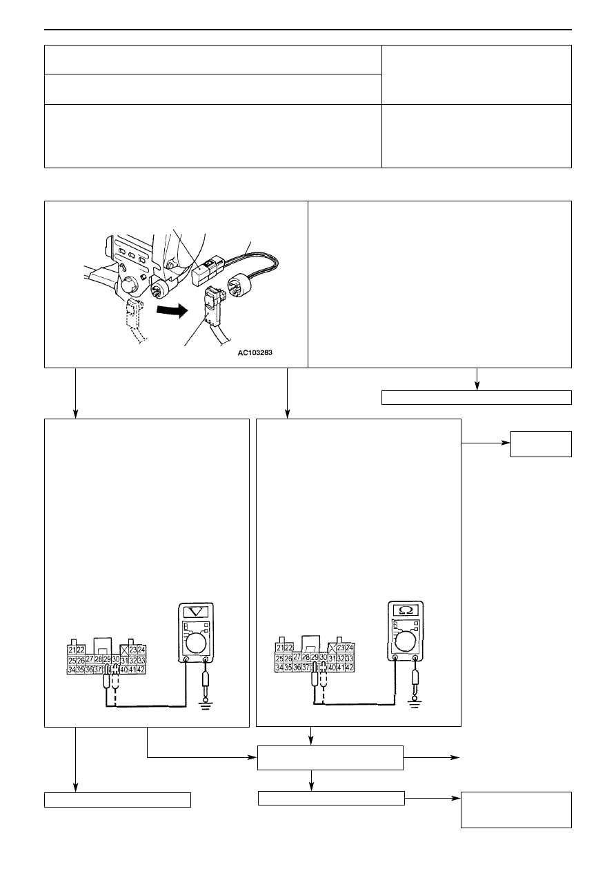
(Checking the circuit between the SRS-ECU
and the driver’s seat belt pre-tensioner)
Measure at the SRS-ECU connector C-124
• Detach the SRS-ECU connector C-124
• Detach the driver’s seat belt pre-tensioner
connector D-02 (see p.52B-34)
• Ignition switch ON
• Measure at harness side
• Voltage between 29, 30 and body earth
Caution
Do not insert the probe, etc. directly into
the terminal from the front side of the
connector, as this may cause a reduction
in contact pressure.
OK: 0V
(Checking the circuit between the SRS-ECU
and the driver’s seat belt pre-tensioner)
Measure at the SRS-ECU connector C-124
• Detach the SRS-ECU connector C-124
• Detach the driver’s seat belt pre-tensioner
connector D-02 (see p.52B-34)
• Measure at harness side
• Voltage between 29, 30 and body earth
Caution
Do not insert the probe, etc. directly into
the terminal from the front side of the
connector, as this may cause a reduction
in contact pressure.
OK: No connectivity
Code No. 66 Driver's seat belt pre-tensioner (squib) system (shorted to
power supply)
Code No. 67 Driver's seat belt pre-tensioner (squib) system (shorted to
earth)
Possible cause
This code is output when the driver's seat belt pre-tensioner (squib) circuit of
the SRS-ECU is shorted to the power supply (Code No. 66) or shorted to earth
(Code No. 67).
• Harness or connector fault
• Shorting of driver's seat belt pre-tensioner
(squib) harness to power supply (Code No.
66) or to earth (Code No. 67)
• SRS-ECU fault
(Checking the driver’s seat belt pre-tensioner (squib))
MUT-II/III diagnosis code
• Connect the dummy resistor (MB991865) to the resistor
harness (MB 991884)
• Detach the driver’s seat belt pre-tensioner connector D-02
(see p.52B-34)
• Connect the resistor harness (MB991884) to the harness
side of the driver’s seat belt pre-tensioner connector D-02
• Connect the (–) terminal of the battery
• After erasing the diagnosis code memory, reconfirm the
diagnosis code.
Is Code No. 66 or 67 output?
Dummy resistor
(MB991865)
Resistance (3
Ω
)
Resistor harness
(MB991884)
D-02 Driver’s seat belt pre-tensioner
connector (harness side)
C-124 connector
C-124 connector
Y1740AU
Y1741AU
Repair
NG
NG
NG
OK
NG
OK
YES (No.66 output)
YES (No.67 output)
NO
OK